#050 Relationship Between Press Machine and Die (8) Relationship Between Material Feeding Device and Press Stroke
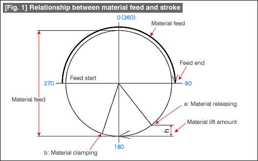
Figure 1 shows the relationship between the material feed and the stroke in a press machine.

The slide of the press machine starts moving down from the top dead center (0° ) and reaches the bottom dead center (180° ). Material feed is started from the mid point (270° ) of the return process, and completes the feeding at the mid point (90° ) of the lowering process (typical timing). The feeding device not only does this kind of simple movement, but also carries out a little more complex movement.
Some feeding error occurs during material feeding. This feeding error does not become a problem if it is a product that is finished in one stroke such as a blanking operation. However, during successive forming, a product gets completed only after several strokes. In such forming, feed errors are not permissible and corrections become necessary. This role is played in a mold by a pilot. A pilot moves the material finely by entering into the pilot holes made in the material thereby correcting the feed errors. If the feeding device is clamping the material at this time, the pilot cannot move the material and correct the error.
It is necessary that the feeding device releases the material at timings matching with the movement of the pilot. This movement is called "material releasing". Usually, material releasing is matched with the position at which the material is lifted in the die (material lifting position). The end of material releasing (material clamping) is done after the slide has passed the bottom dead center.
There are two typical forms of material feeding devices, namely, roll feeder and gripper feeder.
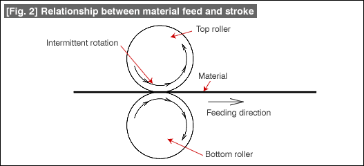
Fig. 2 shows the principles of operation of a roll feeder.

This feeder is made up of a top roller and a bottom roller. The rollers feed the material by intermittently rotating by a distance equal to the feed length.
Unidirectional clutches, various types of cam mechanisms, and servo motors, etc., are used as the means for carrying out intermittent rotation.
Usually, the bottom roller is fixed, and the top roller is pressing against the bottom roller by the force of a spring, etc. For material releasing, the top roller is pushed up using a lever, etc.
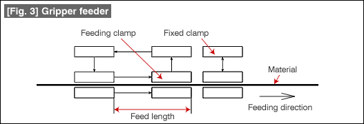
Fig. 3 shows the principles of operation of a gripper feeder.

This feeder has two clamps, namely, a feeding clamp and a fixed clamp. As can be understood from the figure, the feeding clamp repeats the operations of opening >> returning >> closing >> feeding. The fixed clamp goes into the open state when the feeding clamp is carrying out the feeding operation and will be in the closed state during all other operations of the feeding clamp. Next, at the time of material releasing, both the feeding clamp and the fixed clamp carry out the opening and closing operation simultaneously.
The movements of the gripper feeder can be operated using air by switching some valves, or can be carried out using some mechanisms such as cams, etc.
During the operations of material feeding, the position of releasing the material changes depending on the amount of material lift. It is necessary to adjust the timing of releasing to match with those changes.
- #167 Problems in Punching and their Countermeasures (6) Scrap Processing in Punching
- #166 Problems in Punching and their Countermeasures (5) Trimming of Drawn and Shaped Parts
- #165 Problems in Punching and their Countermeasures (4) Scrap Clogging in Punching
- #164 Problems in Punching and their Countermeasures (3) Bending and Twisting of Narrow Punched Parts
- #163 Problems in Punching and their Countermeasures (2) Bending due to Punching


