#017 Calculation of the Deflection of the Moving half Cavity Plate
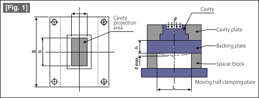
Do you have the experience of flash generated on the periphery of the parting surface of the molded product, or the height dimension of the molded product near the sprue becoming higher? The shape of the moving half cavity plate that is the basis of calculations is shown in Fig. 1.

The maximum deflection δmax occurs along the center line of the cavity plate. The equation for calculating the deflection is as follows.

| B: Width of cavity plate (mm) | b: Width (mm) of the part receiving the cavity injection pressure p | |
| L: Spacing (mm) on the inside of the spacer block | p: Cavity internal injection pressure (kgf/cm3) | |
| h: Thickness of the backing plate (mm) | E: modulus of longitudinal elasticity (Young's modulus) of the material (kgf/cm2) | |
| I: Length (mm) of the part receiving the cavity internal injection pressure p | σmax: Maximum deflection (mm) of the backing plate. |
The important data for E (modulus of longitudinal elasticity ) of the mold plate and p (cavity internal injection pressure) are given below.
|
|
The above equation for calculating the deflection is one for carrying out an approximate calculation. In actuality, since the pocket hole of the slide core and the holes for ejector pins have been formed in the cavity plate, and even the shape of the cavity is not uniform, it can be said that carrying out an accurate calculation of the deflection is actually very difficult. Therefore, the realistic method is to carry out the basic calculation using the approximate equation, and to correct the result to be on the safer side, or to consider factoring in a margin.


