#096 Fundamentals of Press Die Structure Design (5) Method of Selecting the Reference for Machining Plates
A reference is necessary for machining any item. Making the reference vague makes machining difficult, and the desired product may not be obtained. In the case of plates for constructing press dies, there are several methods of selecting the reference.
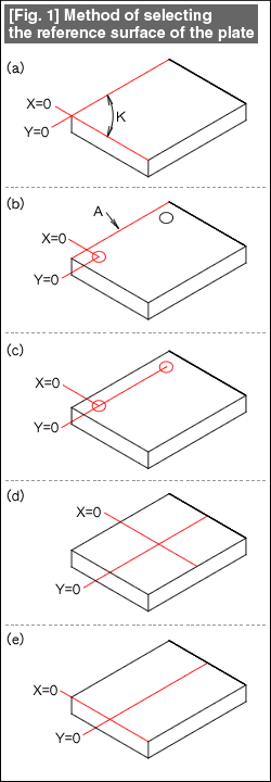
Although each of these methods has its own features, unless there is a unified reference, there will be a lot of confusion in the machine shop, and sometimes this can cause problems in assembling the dies. The types of machining references are shown in Fig. 1. Their features are described below.
Fig. 1(a): Double surface reference. This is the method in which a line parallel to the plate and a perpendicular line are obtained, and the machining is carried out taking the point of intersection between these two lines as the origin. When this origin is used, it is necessary to carry out surface grinding of the plate at two reference planes and to obtain a right angle between them, and the accuracy of these affects the machining accuracy of the plate.
At present, the machining of holes in the plate is done by determining the center by reading the graduations in the machine, and then machining the hole, but previously, marking was done taking two surfaces as the reference thereby obtaining the center of the hole, making a center mark using a center punch, and then machining the hole. The accuracy of the right angle between the two surfaces was reflected as it is in the hole position.
Fig. 1(b): Single surface-hole reference. A parallel line is obtained using one surface of the plate, and the machining is done taking the center of a hole as the reference. This method eliminates the tediousness of obtaining the right angle in the case of double surface reference. This is the method of selecting the reference which assumes that the machining is done after determining the positions of all the holes to be machined in the plate by the table movement of the machining center. Grinding is necessary on the surfaces used for obtaining parallelism. Sometimes, grinding is done on only two end surfaces.

Fig. 1(c): Two hole reference. The lines parallel to the plate are obtained using two holes, and the machining is done taking the center of one hole as the origin. It does not matter what the shape of the peripheral surface of the plate is. For example, it can also be a cut surface as it is.
Fig. 1(d): Double centerline reference. There are two methods of using this reference.
In the method of obtaining the coordinates position by marking, obtaining right angles between the four surfaces of the plate is necessary. A short line is marked at a position thought to be the center of the plate. Next, the same thing is done on the reverse surface by turning the plate upside down (this is called "flipping" in workshop jargon). As a result, if the two short marking lines match, that point becomes the center, and if they do not match, the operation is repeated aiming at the center of the shift between the two lines. Finally, the center is obtained. The reference positions of the X- and Y-axes are obtained by repeating this after rotating by 90°, and machining the hole is done by obtaining the position of the hole taking the point of intersection between the two as the origin. In this method, the errors in the width and length of the plate are distributed between the ends of the plate.
In the other method, a right angle is obtained between two surfaces, and the X- and Y-axes are determined by shifting the coordinates to a position considered to be the center (1/2 of the nominal dimensions), and machining is done taking the point of intersection between the X- and Y-axes as the origin.
This method of selecting the reference is used frequently in single-step type fabrication.
Fig. 1(e): One surface and centerline reference. The method of obtaining the center of the Y-axis is the same as that in the two centerline reference method. The end surface is taken as the reference for the X-axis. In the successive feeding type, the material is machined by placing it at the center of the plate. This method of selecting the reference is being used because it is easy to get used to, since the method of placing the material and the shift of machining matches with the shift of dimensions in the direction of the X-axis.
- #167 Problems in Punching and their Countermeasures (6) Scrap Processing in Punching
- #166 Problems in Punching and their Countermeasures (5) Trimming of Drawn and Shaped Parts
- #165 Problems in Punching and their Countermeasures (4) Scrap Clogging in Punching
- #164 Problems in Punching and their Countermeasures (3) Bending and Twisting of Narrow Punched Parts
- #163 Problems in Punching and their Countermeasures (2) Bending due to Punching


