#099 Fundamentals of Press Die Structure Design (8) Considerations Regarding Die Assembly and Disassembly
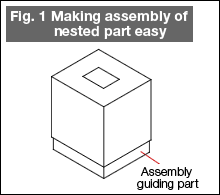
In the preparation of dies, the assembly and disassembly should be easy, and also there should be no fluctuations in the accuracy of the die even if the assembly and disassembly are carried out repeatedly. For example, although an inserted component such as that shown in Fig. 1 is very often pressed into a hole in the plate, if there is no assembly guiding part (which is an all round step of about 0.01 mm), the inserted part becomes slant with respect to the hole and pressing it inside cannot be done properly, and the inside surface of the hole may get damaged.

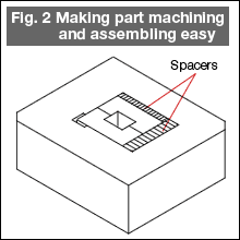
Fig. 2 shows a countermeasure for component machining errors. It is very difficult to finish the machining of the hole and the inserted component accurately to their dimensions in the condition after inserting by pressing. A method that can be thought of is that of matching the actual items by first finishing the hole in the plate and then machining the inserted part while matching it with the hole, but this method cannot be said to be an efficient one. Fig. 2 is a design in which the dimensions from the reference surface are taken of both the hole and the inserted part, the remaining parts are finished with somewhat easier accuracy, and the realization of the pressed and inserted state and error adjustment are carried out using spacers. The efficiency of part machining will be increased. As a consequence of that, to some extent, the load on the die assembling department will increase.

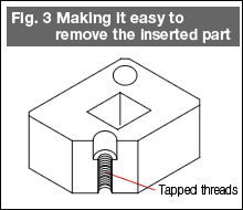
Fig. 3 shows a technique of removing an inserted part that has been pressed inside. Threads are cut by tapping the hole for the bolt for fixing the inserted part, and at the time of removing the inserted part, a bolt is screwed inside this hole and the bolt is pulled to pull out the inserted part. More concretely, if the fixing bolt of the inserted part is of size M4, its hole diameter will be about 4.3 mm. In that hole, a thread of M5 is tapped inside that hole.

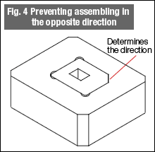
Fig. 4 is a method of fool-proofing so that there is no mistaking the assembling direction of parts. When an assembly requires care to be taken about the direction, some day there will be a mistake in assembling. It is necessary to design so that the assembly can be made only in one direction whoever does the assembling. In a rectangular part, removing the chamfering at any one corner determines the direction of assembling.

The above are some of the aspects to be cautions about. There are many other similar aspects. Take care to attempt to design the parts paying attention to all such aspects.
- #167 Problems in Punching and their Countermeasures (6) Scrap Processing in Punching
- #166 Problems in Punching and their Countermeasures (5) Trimming of Drawn and Shaped Parts
- #165 Problems in Punching and their Countermeasures (4) Scrap Clogging in Punching
- #164 Problems in Punching and their Countermeasures (3) Bending and Twisting of Narrow Punched Parts
- #163 Problems in Punching and their Countermeasures (2) Bending due to Punching


