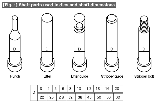
#101 Fundamentals of Press Die Structure Design (10) Dimensions of Shafts Used in Dies
The round parts used in dies are very rarely prepared along with the dies, but are mostly procured as standard parts. Therefore, the dimensions of parts embedded inside the die plate (in this case, these are the shaft dimensions) are organized. The method of organizing is based on the standard size numbers in the Japanese standard (JIS Z 8610). There is a basic series of numbers such as R5, R10, R20, and R40 in the standard. In the case of round parts shown in Fig. 1, the shaft dimensions are determined based on the basic series of R20.
Irrespective of how these were determined, if one keeps these shaft numbers in mind, the design of dies often becomes easy. The die plate size is determined based on the size of the product to be produced by press forming. After that, although the different shaft components are placed in the space of the plate, the decision is made while achieving a balance between the size of the plate and the shaft dimensions. This task becomes easy.

Next, organizing the relationship between the parts and holes, the die design becomes still easier. The relationship between the shafts and the holes is "mating" which can be of the three types of - "a tight fit" (press fit), "a gap fit" (a loose condition in which the hole diameter is larger than the shaft), and "an intermediate fit" (which is a relationship between the hole and the shaft that is in between the first two). For example, when a round punch is to be press-fitted into a punch plate, the reliability of die design will not be stable causing problems if the "fitting margin" is considered each and every time.
If the hole dimension is decided to be shaft - 0.005 mm or shaft - 0.01 mm, not only the speed of designing increases, but also the tools for machining the holes and the machining procedures becomes unified. Carrying this out intentionally is called standardization. When preparing dies using CAD/CAM, if the hold dimensions are determined according to the application taking the shaft dimensions as the reference, the design and fabrication of dies becomes efficient.
- #167 Problems in Punching and their Countermeasures (6) Scrap Processing in Punching
- #166 Problems in Punching and their Countermeasures (5) Trimming of Drawn and Shaped Parts
- #165 Problems in Punching and their Countermeasures (4) Scrap Clogging in Punching
- #164 Problems in Punching and their Countermeasures (3) Bending and Twisting of Narrow Punched Parts
- #163 Problems in Punching and their Countermeasures (2) Bending due to Punching


