#119 Terminology and Surroundings (13) Selection of the Blanking Clearance
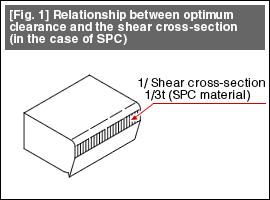
| The discussion here assumes a soft steel material (SPC). In general, when blanking is done using an optimum clearance, a shear cross-section of about 30% of the plate thickness appears in the cut cross-section. The optimum clearance is about 6% to 8% of the plate thickness (Fig. 1). Optimum clearance is a condition that results in the best durability of the tool. Some times there are products in the case where we would like to make the length of the shear cross-section in the cut cross-section longer, or the shear droop smaller. In such situations, we adopt what is called the clearance for fine blanking. This clearance becomes smaller and will be about 3% to 5%. |

|
The above condition is the situation when blanking a shape having straight lines or gradual curves. At corners where two straight lines meet, even when the blanking is done using optimum clearance, the length of the shear cross-section extends to the entire plate thickness (Fig. 2). Under such conditions, there is the problem that the corner part of the punch wears out fast. If a rounding of 50% or more of the plate thickness is provided at the corner parts, the blanked state will be almost the same as in the straight line parts. When rounding cannot be provided at the corner parts, the clearance is made larger at the corners. This additional clearance is about 50% of the clearance used for the straight line parts (Fig. 3).
![[Fig. 2] Shear cross-section of a corner without [Fig. 3] Relationship between a corner without rounding and the clearance [Fig. 2] Shear cross-section of a corner without [Fig. 3] Relationship between a corner without rounding and the clearance](http://www.misumi-techcentral.com/tt/en/press/images/119_2.gif)
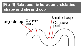
| In the case of an undulating shape as shown in Fig. 4, if a uniform clearance is used, the shear droop becomes larger in the convex part and smaller in the concave part. When it is desired to make the shear droop uniform, the clearance is made larger in the convex part and smaller in the concave part, thereby making the resultant shear droop uniform. |
 |
The changes in the shear droop imply that there are changes in the bending moment and lateral force generated at the time of the blanking operation. Twisting and warping become matters of concern when blanking finely varying shapes. By changing the clearance to match the shape, it is possible to make some improvements. A greater effect can be obtained by combining with pressure pads.
- #167 Problems in Punching and their Countermeasures (6) Scrap Processing in Punching
- #166 Problems in Punching and their Countermeasures (5) Trimming of Drawn and Shaped Parts
- #165 Problems in Punching and their Countermeasures (4) Scrap Clogging in Punching
- #164 Problems in Punching and their Countermeasures (3) Bending and Twisting of Narrow Punched Parts
- #163 Problems in Punching and their Countermeasures (2) Bending due to Punching


