#138 Design of Blanking Dies (11) Design of the Die Holder of a Blanking Die
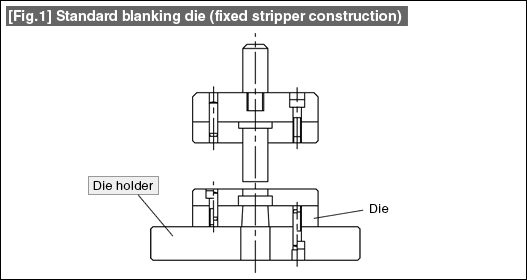
Fig.1 shows the construction of a standard blanking die. The die holder has the role of supporting the bottom die of a blanking die and becomes a clamp part for fixing the bottom die.

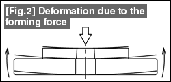
| During blanking, a blanking force such as that shown in Fig. 2 acts on the bottom die. Naturally, the entire plate tries to warp in the opposite direction. Although it is not possible to eliminate this warp, a very small warp is desirable. Since eliminating the warp using only the die plate result in the need to use a large amount of an expensive material, which would be wasteful. The warp is made very small by making the die plate have the minimum necessary thickness and backing it up by the die holder. |  |
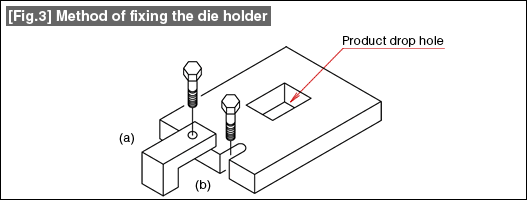
The die holder is also a part for fixing the bottom die. The methods are shown in Fig. 3. (a) This is the method of fixing using a clamp. In this method, if the height (thickness) of the clamp is standardized, the setting up of the dies becomes easy. (b) This is the method of fixing using a U-shaped groove. There will be the restriction that matching will have to be done with the position of the U-shaped groove of the press machine. The depth of the U-shaped groove should be about 2 to 3 times the bolt diameter.

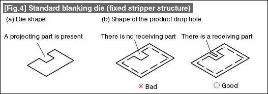
A product drop hole is also necessary in the die holder. While it is desirable that the drop hole is formed in a simple shape such as a round or a rectangle which is easy to machine, in the case of a die shape having a convex part such as that shown in Fig. 4(a), making the drop hole rectangular can cause the convex part to get broken easily (the shape indicated as "Bad" in Fig. 4(b)). Therefore, a projecting part is provided even in the die holder thereby backing up as shown in the shape indicated as "Good" in Fig. 4(b).

- #167 Problems in Punching and their Countermeasures (6) Scrap Processing in Punching
- #166 Problems in Punching and their Countermeasures (5) Trimming of Drawn and Shaped Parts
- #165 Problems in Punching and their Countermeasures (4) Scrap Clogging in Punching
- #164 Problems in Punching and their Countermeasures (3) Bending and Twisting of Narrow Punched Parts
- #163 Problems in Punching and their Countermeasures (2) Bending due to Punching


