#158 Design of Compound Punching Dies (7) Design of a Knockout - 2
The knockout is always in contact with the blank material. The material is often coated with cutting oil, and due to this oil the material adheres closely to the knockout, and even after the product is ejected from the die it sticks to the surface of the knockout, leading to the problem of double product punching (the problem of punching the material again with a product remaining stuck on the knockout), which can break the die. This phenomenon is a kind of trouble that cannot be prevented even when the operator is being cautious. It is preferable to take countermeasures for this in the structure of the die.
As shown in Fig. 1, adhesion of the material to the knockout is prevented by providing a kicker pin in the knockout. When only one kicker pin is provided, it is positioned at the center of gravity, and when several kicker pins are provided, they are positioned considering the balance among them.
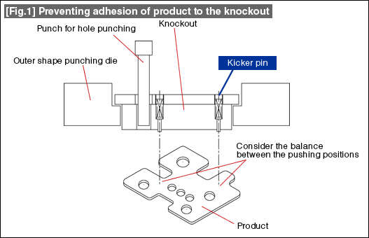
The amount of projection of the kicker pin is about 0.5 mm to 1.0 mm. Even when the product is collected using an air blow, since the form in which the product is separated from the knockout is the same, the direction of flying of the product becomes stable. In the case of a kicker pin with a large amount of projection, the tip of the pin can get caught in a hole in the product when the product is flying away thereby leading to an accident. Therefore, it is preferable to use a smaller amount of projection.
It is not good to make the outer shape of the knockout become completely identical to the shape of the die. The metal shreds, etc., that are generated during the punching operation get inside the gap between the knockout and the die, thereby causing fusing between them. This may also cause the movement of the knockout to become not smooth.
As shown in Fig. 2, the guiding is done by a surface with a stable shape (linear parts, etc.), detailed shape portions or corners are provided with escapes by providing R or C chamfering thereby reducing the parts that can cause problems.
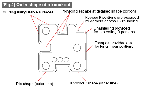
In the escapes for the rounded (R) portions, it is better that the projecting R portions are not escaped by making the rounding R shape small, but by C surfaces. The recess R portions are escaped by providing corners or small R. It is also good to provide escapes in the middle of long straight line portions.

- #167 Problems in Punching and their Countermeasures (6) Scrap Processing in Punching
- #166 Problems in Punching and their Countermeasures (5) Trimming of Drawn and Shaped Parts
- #165 Problems in Punching and their Countermeasures (4) Scrap Clogging in Punching
- #164 Problems in Punching and their Countermeasures (3) Bending and Twisting of Narrow Punched Parts
- #163 Problems in Punching and their Countermeasures (2) Bending due to Punching


Please visit your Regional MISUMI website for additional information or to request our latest catalog.
Unauthorized reproduction is prohibited by all applicable laws and is subject to criminal prosecution.