#022 Basics of Blanking Work (12) Outer Cutting Work - 6: Pilot
In outer cutting work, the cutting is done by moving (feeding) the material by the feed length (the feed pitch) using the side cut or a feeding device. At this time, any fluctuations in the feed pitch will have effect on the product. "Pilot" is used for the purpose of correcting the feed error immediately before carrying out the cutting.
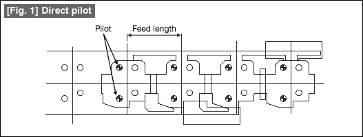
A pilot is basically a round hole, and the error is corrected by inserting a shaft with a pointed tip (a pilot punch) inside this hole. There are two methods of using the hole. The method shown in Fig. 1 is one in which a hole in the product is directly used for correction, and this method is called a direct pilot. Since a hole in the product is used, the shape will be one without any wastage. The drawback of this method is that the hole used for the pilot may get deformed. Care should be taken about this when the material is a soft material such as copper or pure aluminum, etc.

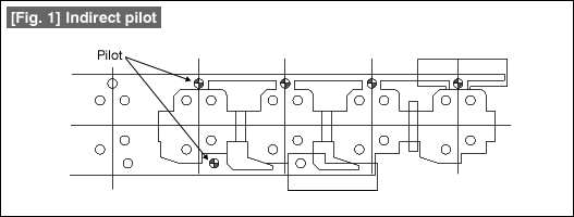
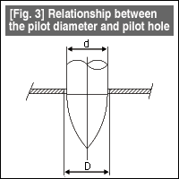
In order to avoid this problem, the form shown in Fig. 2 is one in which a special hole for the pilot is formed in the part that becomes scrap. This is called an indirect pilot. It is possible to determine freely the position and size of the pilot hole. A pilot punch is always inserted into the hole for the pilot immediately after the hole has been punched. If possible, if the pilot is inserted several times in succession, it is possible to reduce the load on each punch. There is a relationship between the diameter of the pilot hole and the diameter of the pilot punch. Although the positioning can be done most accurately when the pilot hole diameter is equal to the pilot punch diameter, the material will be picked up when the pilot punch is coming out of the hole.

| Therefore, the relationship shown in Fig. 3 is used, that is, pilot hole diameter (D) is made greater than the pilot punch diameter (d). If the cut material plate thickness is assumed to be about 1mm, the difference between the two diameters should be about 0.02 when cutting high precision products, and about 0.04 in the case of ordinary precision products. This value is made small when the plate thickness of the material to be worked becomes smaller and is increased when the plate thickness increases. |  |
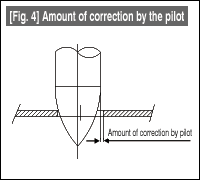
| Figure 4 shows the amount of correction made by the pilot. The feed pitch error is corrected by the tip part of the pilot. The formed shape of the tip part can be the shape of a bullet or the shape of a taper. For the amount of correction, it is better that the diameter of the pilot punch is large, but it is important to achieve a balance with the plate thickness of the material. Assuming a plate thickness of 1mm and a pilot diameter of about 8mm, the amount of correction is in the range of about 0.3 to 0.5. If the amount of correction is large, the pilot punch gets worn out faster. |  |
- #167 Problems in Punching and their Countermeasures (6) Scrap Processing in Punching
- #166 Problems in Punching and their Countermeasures (5) Trimming of Drawn and Shaped Parts
- #165 Problems in Punching and their Countermeasures (4) Scrap Clogging in Punching
- #164 Problems in Punching and their Countermeasures (3) Bending and Twisting of Narrow Punched Parts
- #163 Problems in Punching and their Countermeasures (2) Bending due to Punching


