#063 Method of Using Standard Components (12) Round Punches - 1
In JIS standards, round punches are classified as "dies" among "tools" of the category S. The JIS number is B5009. Although initially the name was "round punch for press dies", it has been changed at present to "punch with flange for press dies".
Initially in JIS a total of three types were determined as the standard types from the shapes shown in Fig. 1 with two types from the shape of Fig. (a) and one type from the shape of Fig. (b).

One type from Fig. (a) has all its dimensions determined, with the round tip diameter ranging from 1.0mm to 4.0mm in steps of 0.1mm, and those with higher diameters were standardized up to 24mm with suitable intervals between them. These were the first standardized round punches. Because of the low degree of freedom during use, they have been deleted from the current JIS standards. Another standard is one in which it is possible to select freely the tool tip dimensions with a certain width relative to the shank diameter of the round punch. This is the base for the shoulder punches of Misumi. In the standards of shoulder punches, it is possible to select more types than in JIS.
Even in the standards of the type from Fig. (b) all the dimensions have been determined, and there were standards of diameter from 0.1mm to 4.9mm in steps of 0.1mm. At present, these have been deleted from the standards. Misumi has standards as mini straight punches.
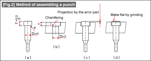
Tolerance in the positive direction has been determined for the thickness (T) of the flange part of Fig. (a). Although initially this was +0.3/0, at present, it has been changed to +0.25/0. The explanation why the flange part is the press tolerance is given

Although countersinking is made in the formation of the hole in which the punch enters as shown in Fig. 2(b), countersinking is a procedure that is relatively poor in accuracy. Since it is difficult to eliminate the gap between the punch and the hole, always the assembly should be made so that the flange part of the punch projects up, and after that, as a rule, in the assembled state, the projecting part should be made flat by grinding. (This method of assembling was common when this standard was prepared.) This thinking is still being carried on.
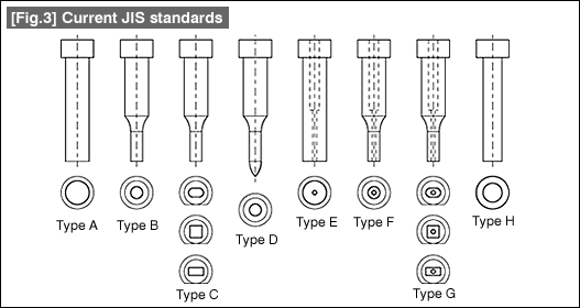
The current JIS standards are of the types shown in Fig. 3.

The number of types has increased, and it appears that it is possible to meet a variety of applications. In addition, although matching with ISO has been implemented, because of that there appears to be some part that is difficult to use. This is the overall length of the punch.
The earlier length standards were 40, 50, and 60, but gradually lengths matching with the standards have come into use, for example, the lengths of 56, 63, and 71, and the lengths 50, 60, and 70 are not present. In the actual practice the previous overall lengths are still being used, and it is convenient because it is possible to specify the length freely.
- #167 Problems in Punching and their Countermeasures (6) Scrap Processing in Punching
- #166 Problems in Punching and their Countermeasures (5) Trimming of Drawn and Shaped Parts
- #165 Problems in Punching and their Countermeasures (4) Scrap Clogging in Punching
- #164 Problems in Punching and their Countermeasures (3) Bending and Twisting of Narrow Punched Parts
- #163 Problems in Punching and their Countermeasures (2) Bending due to Punching


