#069 Method of Using Standard Components (18) Misfeed Detection Unit
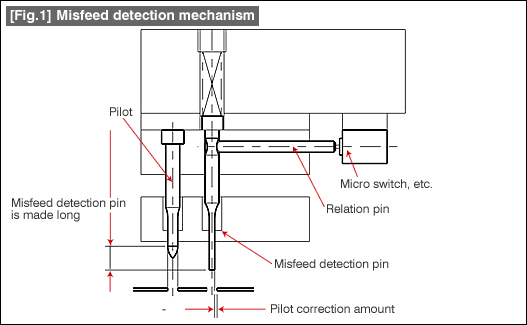
The relationship between the misfeed detection unit and the pilot is shown in Fig. 1.

The misfeed detection is made to operate in the state in which the pilot cannot correct the position of the fed material. Therefore, since it is made to act earlier than the pilot, it has to be made longer and thinner than the pilot (within the correction amount of the pilot). The general form of a misfeed detection unit is constituted from a misfeed detection pin, a relation pin, and a micro switch, etc.
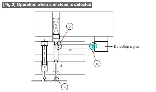
Fig. 2 shows the state in which a misfeed has been detected.

The operation is made in the following sequence
| (a) ↓ | The misfeed detection pin climbs over the edge of the pilot hole of the shifted material. | |
| (b) ↓ | The misfeed detection pin is pushed up. | |
| (c) | The relation pin set in the groove of the misfeed detection pin is pushed sideways and presses a micro switch, etc., outputs the detection signal, which stops the press machine. |
After detecting a misfeed, although it is good that the press machine is stopped before the pilot contacts the material, in order to do that, it is necessary that the misfeed detection pin is considerably longer than the pilot. The conditions are very often difficult to realize, and it is often assumed that the machine stops after making one wrong press operation. In the case of a high speed press machine, even if a sudden stop is made, the machine stops after making two or three wrong press operations. In the method of misfeed detection explained using Fig. 1 and Fig. 2, there is some play in the movements of the misfeed detection pin, the relation pin, and the micro switch, etc. Since there is a delay in the detection time corresponding to this play in the movement, the stopping of the press machine becomes late, and the wrong press operations become more.
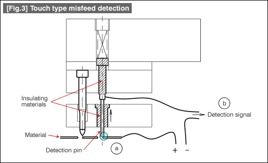
The mechanism in Fig. 3 has been made to operate electrically considering the problem of delay in the mechanical operations.

The example shown in the figure is merely one of the possible examples, and a form with many modifications is used. The principle of operation is that the detection pin is maintained in the insulated state, and a small current is passed between the material and the detection pin. Under normal conditions, no current flows because the detection pin enters the pilot hole without touching the material. If the pilot hole gets shifted as shown in Fig. 3(a) and contacts the detection pin, a current flows, and a detection signal is output stopping the press machine. Faster operation can be obtained compared to Fig. 1. The drawback is that the electrical lead wire of the detection pin is moving all the time during press operation. As a consequence of this, the lead wire is likely to get cut somewhere. If this happens, even if the detection pin detects an abnormality, the press machine cannot be stopped. Periodical checks cannot be avoided.
- #167 Problems in Punching and their Countermeasures (6) Scrap Processing in Punching
- #166 Problems in Punching and their Countermeasures (5) Trimming of Drawn and Shaped Parts
- #165 Problems in Punching and their Countermeasures (4) Scrap Clogging in Punching
- #164 Problems in Punching and their Countermeasures (3) Bending and Twisting of Narrow Punched Parts
- #163 Problems in Punching and their Countermeasures (2) Bending due to Punching


