#080 Method of Using Standard Components (29) Pilot - 4: Countermeasures against Thin Plate Material Deformations and Material Pulling Up
In continuous press operation, the material is lifted slightly up from the die surface and moved. Lifting up the material from the die surface is called "Lift up". The pilot provided in the top mold moves down and inserts the pilot in the material that is in the lifted up state. If the material has sufficient thickness, because of the strength of the material, it is possible for the pilot to enter the material without deforming the material. However, since instability is caused if the positions of the guide lifter and the pilot hole are separated far apart, the positions of the pilot hole and the guide lifter should be as close to each other as possible, thereby making the material deformation small. If the material becomes thin, even if the guide lifter is made to come close, the material gets deformed by being pressed by the pilot as shown in Fig. 1(a). If this happens, since the pilot does not enter into the hole properly, it can lead to wrong punching. Even if it does enter properly, as shown in Fig. 1(b), the material will be lifted up by the pilot during the returning operation after punching, and again this can cause more wrong operations.

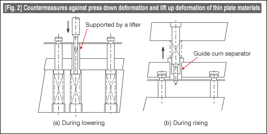
As a basic countermeasure against these problems, the surface of the pilot is polished well and the contact resistance is made low. A fundamental countermeasure is to strengthen the weak parts. A concrete example of this is shown in Fig. 2.

Fig. 2(a) is a measure of supporting from below due to being pushed down from above. A lifter is also used as a lifting up part. While a normal lifter functions for lifting up, if a hole is provided in the lifter and the tip of the pilot is made to enter in it, it becomes possible to use a lifter below a pilot, and since the material is supported without getting bent, it becomes possible to pilot the material in a stable manner. Such a lifter is called a "lifter with hole below the pilot".
Fig. 2(b) is a measure for preventing the lifting up of the material in the returning process. The pilot guide is placed inside the stripper. This guide is supported by a spring. In a normal pilot, a straight part should be coming out from the stripper surface. While the positioning is done using this part, even the lifting up of the material is done using this part. The pilot guide incorporated into the stripper is made movable (spring supported), and the tip of the guide is lowered to the guide part of the tip of the pilot.
By doing this, it is possible to prevent lifting up of the material. If the guide is lowered to the tip of the pilot, there will be problems at the time that the pilot enters the hole. Therefore, the spring supporting the pilot guide is made extremely weak. If this form is used in combination with the lifter with a hole below the pilot, the result will be perfect.
It is also important to change the surrounding conditions of a pilot to match the conditions of use.
- #167 Problems in Punching and their Countermeasures (6) Scrap Processing in Punching
- #166 Problems in Punching and their Countermeasures (5) Trimming of Drawn and Shaped Parts
- #165 Problems in Punching and their Countermeasures (4) Scrap Clogging in Punching
- #164 Problems in Punching and their Countermeasures (3) Bending and Twisting of Narrow Punched Parts
- #163 Problems in Punching and their Countermeasures (2) Bending due to Punching


