#145 Design of Hole Punching Dies (5) Design of Movable Strippers of Hole Blanking Dies
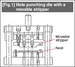
| In the case of a hole punching die as shown in Fig. 1, the hole punching is done by placing the blank on the die. When wanting to maintain the flatness of the product (blank), anybody will think of carrying out the pressing operation while keeping the blank fixed. This is the concept behind the die structure shown here. This is called the movable stripper structure. The stripper with the role of peeling off the material from the punch is always present on top of the die, and since the punch passes through the stripper, it is ideal for pressing down the blank. In order to make the stripper movable, the stripper is held at a fixed position by a stripper bolt. The holding position is very frequently such that the stripper surface is 1mm lower than the tip of the punch. The force with which the stripper presses the material is obtained by a spring. A spring is assembled behind the stripper. At this time, the spring is compressed slightly. The strength of the spring arising out of this compression is called the "initial pressure". The initial pressure is made 15% or more of the hole punching force (this can be 3% or more of the blanking force if it is only sufficient to peel off the material from the punch). The material is pressed with a certain fixed pressing force so that there is no deformation associated with the hole punching operation. This is the purpose of the initial pressure. |  |
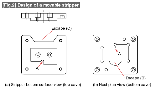
See Fig. 2. When the positioning of the blank is done by a plate nest, it is necessary to scrape the stripper surface into a convex shape to match with the shape of the nest. Very often an end mill is used for machining this shape. The convex shape of the stripper and the shape of the nest are designed so that this machining becomes easy. The peripheral part called the flange of the convex shape becomes thin due to the machining of the convex part of the stripper. If this becomes too thin, it will affect the strength of the stripper. Determine the thickness considering the balance. The part shown as the escape in (C) of Fig. 2 is a part that comes before the die. Safety and security during work is obtained by providing this escape.

- #167 Problems in Punching and their Countermeasures (6) Scrap Processing in Punching
- #166 Problems in Punching and their Countermeasures (5) Trimming of Drawn and Shaped Parts
- #165 Problems in Punching and their Countermeasures (4) Scrap Clogging in Punching
- #164 Problems in Punching and their Countermeasures (3) Bending and Twisting of Narrow Punched Parts
- #163 Problems in Punching and their Countermeasures (2) Bending due to Punching


