#160 Design of Compound Punching Dies (9) Design of a Knockout - 4
A compound punched product is in the state in which it has been pushed inside the die and is pushed up by the knockout, but is staying inside the die due to the force of friction with the die. In Tutorial #154, we have explained the relationship between the press machine and the knockout. Please refer also to that tutorial and read the following.
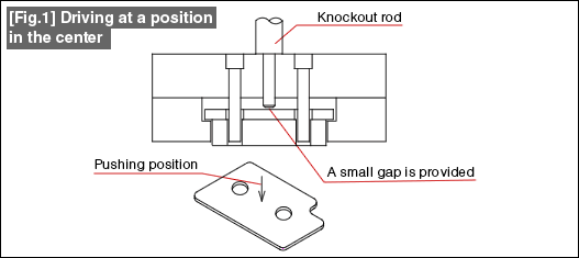
In the shape shown in Fig. 1, since there is a gap at the center of the knockout, it is possible to press the knockout directly with the knockout rod. If it is possible to adopt this method, it is possible to simplify the die structure.

If the knockout rod is stepped and is pushed too abnormally, the knockout is prevented from being affected because the step in the knockout rod receives that abnormal push. In addition, even when there is no abnormality, a slight gap is provided between the knockout and the tip of the knockout rod so that the knockout is not pushed more than necessary. The size of this gap is less than the length by which the knockout comes out of the die surface (see Tutorial #158).
The precaution in this method of pushing at the center is that even the positions of the holes in the product should be balanced. A lopsided placement of holes wherein the holes are more in some parts is not good because then a force will always act to make the knockout get tilted. In such shapes, it is necessary to adopt the method shown below.
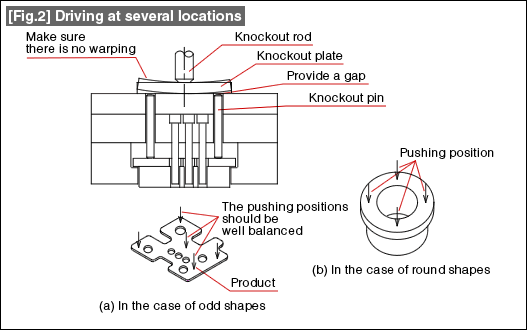
Fig. 2(a) shows the most commonly used structure for driving a knockout. Several knockout pins are provided considering the balance between the shape of the product and the placement of holes so as to push down the product in a balanced manner. In Tutorial #160, even in the method of supporting the knockout by suspension bolts, the placement of the suspension bolts is also made as per the above description.
Even in this case, the knockout pin is made slightly short thereby ensuring that the knockout is not pushed too much.
The knockouts will be placed in a circular fashion when forming round shapes such as washers, etc, and three or four pins are positioned as shown in Fig. 2(b).

The knockout pin transfers the force of the knockout rod via the knockout plate. The knockout plate can get warped if it is too thin. Take care about this.
It goes without saying that the lengths of all knockout pins are the same.
- #167 Problems in Punching and their Countermeasures (6) Scrap Processing in Punching
- #166 Problems in Punching and their Countermeasures (5) Trimming of Drawn and Shaped Parts
- #165 Problems in Punching and their Countermeasures (4) Scrap Clogging in Punching
- #164 Problems in Punching and their Countermeasures (3) Bending and Twisting of Narrow Punched Parts
- #163 Problems in Punching and their Countermeasures (2) Bending due to Punching


