#161 Design of Compound Punching Dies (10) Stripper and Material Guide
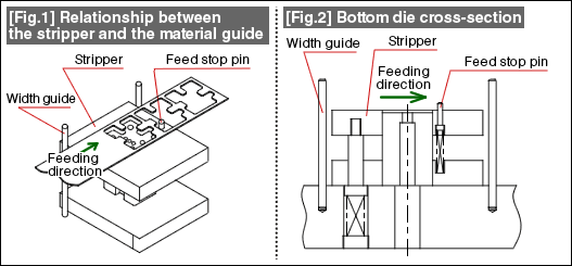
The material guide in a compound punching die is discussed in this tutorial. Fig. 1 shows the state in which forming is being done using a compound punching die. The cross-section of the corresponding bottom die structure is shown in Fig. 2.

The material moves above the stripper plate. The width guide of the material is frequently constituted by a round rod, etc., placed only on one side. This is in order to be compatible with changes in the material width and because it would be convenient while taking out the product. In specific terms, in the case of forming with fixed length materials and when the product is large and falls down after being ejected from the top die above on to the material on the bottom die, the product on the material is blown so that it falls outside the die and can be collected. Since this type of operation becomes difficult to carry out if the material width is firmly guided, it is common to guide the material along the width direction only on one side. There is also the intention of eliminating the need to put a hand inside the die to take out the product. There is no problem even if the material is firmly guided along its width if the product has a size that makes it possible to be blown away by an air blast.
The positioning in the feeding direction is done by a stop pin. A stop pin is not necessary when forming using a feeding device that feeds a coil material for forming. But a stop pin is necessary when fixed length material is being worked manually. A stop pin is placed at a position where the shape is stable. Very often the stop pin is made of the movable type.
In compound punching, measures are taken so that some slight variations in the positioning do not cause any problems by having a slightly wider bridge than in blanking.
The stripper surface is made about 0.5 mm to 1.0 mm higher than the outer shape punching punch surface so that the material feeding is not obstructed. The hole in the stripper in which the punch for outer shape punching passes through is not matched exactly as in the relationship between the die hole and the knockout, but escapes are provided in some parts thereby ensuring that there is no occurrence of fusing of biting of the punch for outer shape punching and the stripper.
The stripper has the functions of both stripping and lifting.
- #167 Problems in Punching and their Countermeasures (6) Scrap Processing in Punching
- #166 Problems in Punching and their Countermeasures (5) Trimming of Drawn and Shaped Parts
- #165 Problems in Punching and their Countermeasures (4) Scrap Clogging in Punching
- #164 Problems in Punching and their Countermeasures (3) Bending and Twisting of Narrow Punched Parts
- #163 Problems in Punching and their Countermeasures (2) Bending due to Punching


