#251 Basic Elements of Automation Clever Mechanisms:Rotary-Linear Motion Conversion Mechanism 1
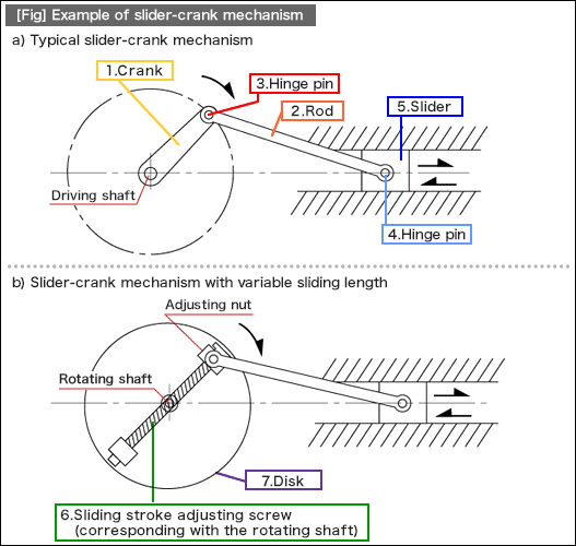
[Fig] a) is a slider-crank mechanism, which is a typical structure converting rotary motion into linear motion, achieved by connecting a slider and a crank with a rod. This mechanism is also utilized as a system that converts reciprocating linear motion of an automobile engine into rotary motion. (See [Fig.1] a.)
[Fig] b) is an example of the mechanism that has the same functions as [Fig] a), in addition to the sliding stroke adjustment feature for the slider. To add this feature, the sliding stroke adjusting screw is placed on top of the rotation shaft center of the rotation disk. The sliding stroke can be adjusted by the adjusting nut located on one end of the sliding stroke adjusting screw. This is an effective method if the mechanism shown in [Fig] a) needs to have a function that is compatible with various models. In addition, if high-speed rotation or operation for long hours is required, it is necessary to consider design items related to the reliability matters described here.
| 1. | Rotation balance of rotating body (the entire structures on the disk) | |
| 2. | Strength of rotating shaft | |
| 3. | Prevention of adjusting nut-loosening (e.g. double-nut system) | |
| 4. | Selection of wear-resistance parts for the area subject to wear |

•Example of standard component uses
|
- Positioning technology
- Designing and processing
- Sensor Technology
- Automation elements technology
- Clean room technology
- Design hints
- Design tips
- Designing and Machining
- Drive mechanism design
- Hints on designing
- Linear Motion Components
- Locating Technology
- Manufacturing technology
- Motion mechanism design
- Pneumatic Drives
- Production Technology
- Technology Outlook
- General description
- Low-cost automation and materials
- Transfer LCA
- #333 Know-how on automation: Pressurized heating technology - 5: Multilayer pressurized heating process technique
- #332 Know-how on automation: Pressurized heating technology - 4: Points to remember when designing mechanism of pneumatic pressurization method
- #331 Know-how on automation: Pressurized heating technology - 3: Pneumatic pressurization method and pressure profile
- #330 Know-how on automation: Pressurized heating technology - 2: Pressurization method and pressure profile
- #329 Know-how on automation: Pressurized heating technology


