HOME > Low Cost Automation Tutorial > #208 Design Image Training - 24: Design Drawing Method for Movable Body
Low Cost Automation Tutorial
#208 Design Image Training - 24: Design Drawing Method for Movable Body
Category : Hints on designing
July17, 2015
When designing machinery equipment containing a movable body, the designer needs to check in the early stages of the designing process that unforeseen problems do not occur throughout the moving range of the movable body. This section introduces the design technique for a movable body.
- Two-dot chain lines (also called imaginary lines) are used for illustrating the operating state. Dashed lines (also called hidden lines) are used for illustrating invisible (hidden) structures.

- Draw a two-dot chain line (imaginary line) to illustrate the maximum stroke position in the movable range when designing a movable body in the assembly diagram.
- The designer must check that the condition of the movable body does not cause any structural problems at this maximum stroke position.
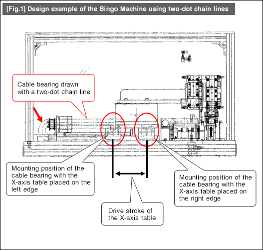
- In the example of the Bingo Machine shown in [Fig.1], two-dot chain lines indicate the cable bearing state at the maximum stroke position of the X-axis table.
- Based on the state of the two-dot chain lines in [Fig.1], you can verify the following:
(1) It is designed with sufficient room that the cable bearing does not touch the cover even when the X-axis table moves to the leftmost position.
(2) In the plan view seen from above (not [Fig.1]), the cable bearing does not get in the way of the manifold regulator of the air cylinder installed on the back.
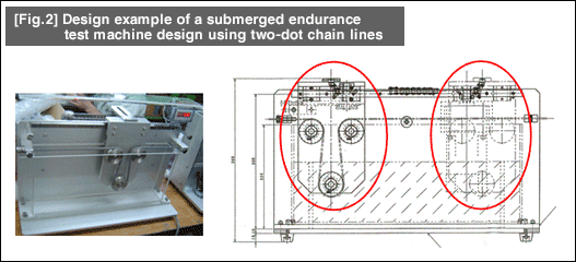
- [Fig.2] is an example of the submerged endurance test machine. The movable body is illustrated at two positions: left end (solid line) and right end (two-dot chain line).

- Positioning technology
- Designing and processing
- Sensor Technology
- Automation elements technology
- Clean room technology
- Design hints
- Design tips
- Designing and Machining
- Drive mechanism design
- Hints on designing
- Linear Motion Components
- Locating Technology
- Manufacturing technology
- Motion mechanism design
- Pneumatic Drives
- Production Technology
- Technology Outlook
- General description
- Low-cost automation and materials
- Transfer LCA
- #333 Know-how on automation: Pressurized heating technology - 5: Multilayer pressurized heating process technique
- #332 Know-how on automation: Pressurized heating technology - 4: Points to remember when designing mechanism of pneumatic pressurization method
- #331 Know-how on automation: Pressurized heating technology - 3: Pneumatic pressurization method and pressure profile
- #330 Know-how on automation: Pressurized heating technology - 2: Pressurization method and pressure profile
- #329 Know-how on automation: Pressurized heating technology


