#262 Basic Elements of Automation Clever Mechanisms: Boost Mechanism -1
A mechanism designed to generate a large force from a small force is called a boost mechanism. Mechanical components that constitute this boost mechanism include links, levers, screws, wedges, gears, and pulleys. For lightweight arms of robots entered in the Robocon robot contest, the link mechanism is frequently adopted for its boosting effect produced from the simple structure.
Lifting up a heavy load using a lever is also an application example of this boost mechanism. In this case, you will be able to lift up a heavy load with a small force, but you will need to apply the force for a longer distance than when you carry the heavy load itself.
As you already know, using the boost mechanism does not change the workload (the force required for moving an object multiplied by the travel distance).
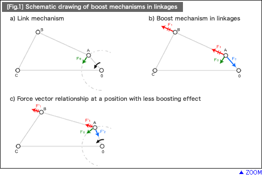
Now, let's take a look at the link mechanism consisting of four-bar linkages in [Fig.1] - a) and consider how the force vector is applied at Joint A.
[Fig.1] - b) is the schematic layout of a link mechanism generating a high degree of boosting effect.
[Fig.1] - c) is the schematic layout of a link mechanism generating little boosting effect.
Let's compare their force vector components at Joint A.
In [Fig.1] - b), "Crank OA" and "Link AB" form an angle of approximately 180 degrees (close to a linear arrangement) whereas "Link AB" and "Lever BC" are almost perpendicular to each other. In this case, if "Torque T" applies to "Driving Shaft OA" and Force F0 applies to the tangential direction of "Joint A", Force F1 applied to "Link AB" on "Joint A" will be 2.7 times greater than the tangential force F'0 based on the vector components at "Joint A".
In [Fig.1] - c) on the other hand, Force F'1 applied to "Link AB" on "Joint A" is only 1.1 times greater than the tangential force F'0.
As seen in this example, using the link mechanism to form the relationship shown in [Fig.1] - b), allows effective construction of the boost mechanism. In addition, when the link mechanism is applied to the boost mechanism, all the rotary couplers (in pairs) and the links must be designed with enforced strength.
In the next volume, we will look at an application example of the boost mechanisms using a crank.
- Positioning technology
- Designing and processing
- Sensor Technology
- Automation elements technology
- Clean room technology
- Design hints
- Design tips
- Designing and Machining
- Drive mechanism design
- Hints on designing
- Linear Motion Components
- Locating Technology
- Manufacturing technology
- Motion mechanism design
- Pneumatic Drives
- Production Technology
- Technology Outlook
- General description
- Low-cost automation and materials
- Transfer LCA
- #333 Know-how on automation: Pressurized heating technology - 5: Multilayer pressurized heating process technique
- #332 Know-how on automation: Pressurized heating technology - 4: Points to remember when designing mechanism of pneumatic pressurization method
- #331 Know-how on automation: Pressurized heating technology - 3: Pneumatic pressurization method and pressure profile
- #330 Know-how on automation: Pressurized heating technology - 2: Pressurization method and pressure profile
- #329 Know-how on automation: Pressurized heating technology


