#053 Method of Using Standard Components (2) Method of Using Lifters and Guide Lifters
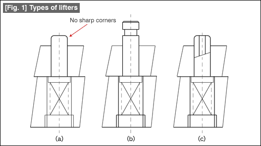
Figure 1 shows the types of lifters. A lifter is a component for supporting the material inside the die so that it does not sag or tilt. A lifter can be of the round type or of the square type.

(1) Method of using lifters
Sharp corners are not allowed in the surfaces of lifters that come into contact with the material and these parts should be rounded (see Fig. 1). This is to make sure that no scratches are formed on the material.
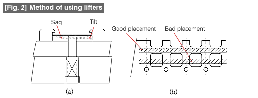
In the dies for successive feeding, very often it is necessary to make the material in the die float above the surface of the die. This is for feeding the material. This is also commonly true for transfer dies, dies for robot machining. Lifters are placed in a balanced manner so that the material does not sag or get tilted as shown in Fig. 2(a). The precaution in the placement of lifters in a mold for successive feeding is shown in Fig. 2(b). The lifters are placed and fixed so that they do not interfere with the material during its feeding (the part showing good placement).

(2) Method of using guide lifters
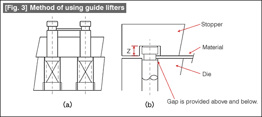
As is shown in Fig. 3(a), guide lifters are components that carry out the functions of both a material guide along the width direction and a lifter. The basic principle is to place them so that there is no sag in the material.
Fig. 3(b) shows the relationship in the up and down directions. When the material is on the die surface, guide gaps of the guide lifter are provided above and below the material as is shown in the figure. If care is not taken about this, the guide lifter can cause crescent shaped scratches or deformations in the material. Sometimes, the material may also be cut in the shape of a crescent moon.
The pressing down of the guide lifter is made at the head part of the lifter. Measures should be taken so that there are no fluctuations in the depth Z machined in the stopper. Take care so that the pushing direction is not tilted because this can cause breakage of the head of the guide lifter.

(3) Relationship between lifters and pilots
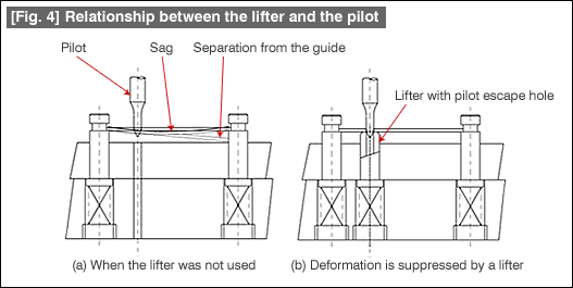
When forming thin plates, if a pilot enters in the lifted condition as is shown in Fig. 4(a), it causes various problems such as the material sagging or becoming tilted, thereby it can dislodged from the guide lifter, etc. As a countermeasure for this, there are lifters with escape holes for pilots. The material becomes stable because it is supported from below when a pilot enters the material. It is good to use this as far as possible while forming thin plates.

- #167 Problems in Punching and their Countermeasures (6) Scrap Processing in Punching
- #166 Problems in Punching and their Countermeasures (5) Trimming of Drawn and Shaped Parts
- #165 Problems in Punching and their Countermeasures (4) Scrap Clogging in Punching
- #164 Problems in Punching and their Countermeasures (3) Bending and Twisting of Narrow Punched Parts
- #163 Problems in Punching and their Countermeasures (2) Bending due to Punching


