#054 Method of Using Standard Components (3) Method of Using Lifters with Air Holes
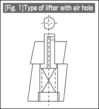
| Fig. 1 shows a lifter with an air hole. This is a component obtained by providing an air hole in and a measure to stop the rotation of an ordinary lifter. |  |
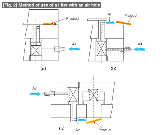
Figs. 2(a) and 2(b) show the conditions of use.

Air is fed from outside to the lifter part. When the die is at the bottom dead center, the air hole is closed automatically since the lifter is pushed up, and hence air does not come out [Fig. 2(a)]. When the top die rises from the bottom dead center, air is blown out from the air hole, and the product that has been cut and separated is blown off [Fig. 2(b)]. At this time, the stopper is still rising. The ejected air flows between the die and the stopper. Because of this, the flow stabilizes and even the blowing off of the product becomes stable.
Although the flow of the air blowing from outside near the top dead center gets dispersed and the flying off of the product is not stable, the above method not only avoids this drawback but also shortens the time required for setting up the die.
Fig. 2 shows the method of use as an air blow in a blanking die or an upward drawing die. Although the name "lifter" gives the impression that it is used in a bottom die, this is a method of use considering it as an air nozzle. Since air is blown near the product, the flying off of the product becomes stable. As was explained above, it becomes unnecessary to set up a separate air nozzle for the product, and the setting up time becomes shorter.
- #167 Problems in Punching and their Countermeasures (6) Scrap Processing in Punching
- #166 Problems in Punching and their Countermeasures (5) Trimming of Drawn and Shaped Parts
- #165 Problems in Punching and their Countermeasures (4) Scrap Clogging in Punching
- #164 Problems in Punching and their Countermeasures (3) Bending and Twisting of Narrow Punched Parts
- #163 Problems in Punching and their Countermeasures (2) Bending due to Punching


