#056 Method of Using Standard Components (5) Clamping Screws (Hexagonal Bolts with Holes)
In press dies, for some unknown reason, hexagonal bolts with holes (JIS B 1176) are used as the clamping screws. Hexagonal head bolts and countersunk screws were being used in the olden days, but naturally over time, these have become the standard components. For the descriptions of the detailed standards of hexagonal headed bolts with holes, see the JIS standards or the technical data part of the Misumi catalog "Face".
Unfortunately, there are no documents that clearly describe the method of using clamping screws. Because of this, the designers of dies are forced to worry that they do not this but cannot go and ask for such simple information. Take heart, because everybody is in the same situation in the beginning. One gradually comes to know the method of use.
Coming to the point, the methods of using clamping screws can be divided broadly into two methods, that of plate components and block components.
(1) Clamping screws of block components (nested, punch, etc.)
There are a large number of methods of using clamping screws in the case of block components as shown in Fig. 1.

Taking the minimum value of the dimension A in the figure as the screw diameter (D), the thickest screw that can be used is selected from the size of the block (screw breaking countermeasure).
When there are large and small blocks present simultaneously in a die, if the screw size is determined individually for each block, there will be a mix of thick and thin screws, which makes it inconvenient during assembly and disassembly of the die, and hence it is recommended to use screws of the same size.
(2) Clamping screws of plate components
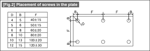
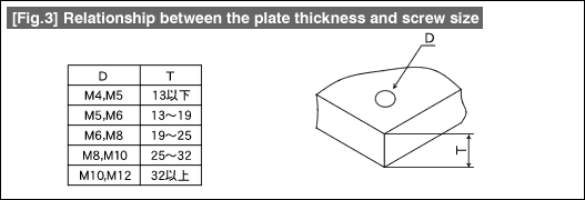
In the case of plate components, as is shown in Fig. 2, the screw size is determined considering the combination of the relationships among the dimension B from the edge of the plate, the pitch F of the screws, and the plate thickness shown in Fig. 3. It is easier to understand if attention is paid to the dimension W of the plate, the dimension B is made about twice the smallest value, and the decision is made considering the relationship between the dimension F and the plate thickness.


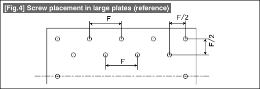
When the plate becomes big, it becomes insufficient to place the screws only near the periphery. In such situations, determine the placement of screws inside the plate such as in the example shown in Fig. 4.

(3) Screw diameter and tap depth
There is a certain depth of penetration of the screw for every screw diameter at which there is no problem in the clamping. This is related to the depth up to which thread tapping is done. In general, the tap depth is taken to be about 1.5 to 2.5 times the screw diameter, the minimum depth of insertion of the screw is taken to be about the same as the screw diameter, and about two times the screw diameter when the screw is inserted deeper. Unless there is some special problem, it can be taken to be a standard of clamping if the depth is more than 1.5 times the diameter of the screw.
- #167 Problems in Punching and their Countermeasures (6) Scrap Processing in Punching
- #166 Problems in Punching and their Countermeasures (5) Trimming of Drawn and Shaped Parts
- #165 Problems in Punching and their Countermeasures (4) Scrap Clogging in Punching
- #164 Problems in Punching and their Countermeasures (3) Bending and Twisting of Narrow Punched Parts
- #163 Problems in Punching and their Countermeasures (2) Bending due to Punching


