#133 Design of Blanking Dies (6) Design of Punch Plates
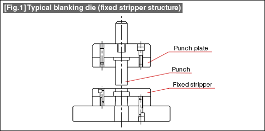
The designing of a punch was described in CourseNo. 129. At that time, it was explained that when the punch becomes small it becomes difficult to hold it independently, and that therefore the method is used of fixing it by embedding it in a plate. This plate that holds the punch is called a punch plate. Fig. 1 shows a typical construction of a fixed stripper type structure using a punch plate.

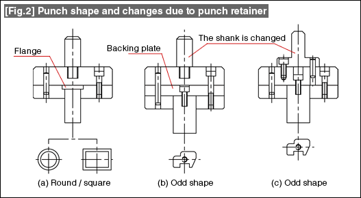
In the fixed stripper structure, the position and the verticality of the punch is provided by the punch plate. In this method, the punch is lightly press-fitted into a hole in the punch plate. Light press-fitting is driving the punch inside the hole by hitting it lightly. Hard press-fitting is not desirable because it causes the punch plate to get warped or deformed. It is also necessary to consider preventing the punch from coming out the hole and dropping off (punch retainer). The details of this in terms of the relationship between the shape of the punch and the punch retainer are shown in Fig. 2.

The method (a) is an example of punches with simple shapes such as round and square. Such punches are very often prevented from falling off by providing a flange in the punch as a punch retainer. The method (b) is an example of an odd-shaped punch which is formed by electrical discharge wire-cut machining. Threads are cut in the punch and the punch is fixed to the punch plate (backing plate) using a bolt so that the punch is retained. The method (c) is an example in which the cross-sectional area of the punch is relatively large. When the cross-sectional area of the punch becomes large, the backing plate is eliminated, and the punch is directly fixed to the punch holder. A method of fixing by bolts is shown here for retaining the punch. See the changes in the shank by comparing the figures (b) and (c). This example is shown here as one in which the method of attaching one component also affects other components and changes them.
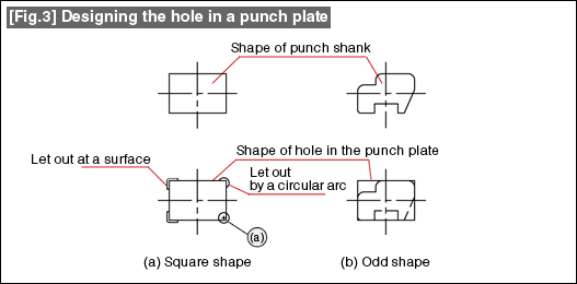
Fig. 3 is an example of designing the hole in a punch plate.

Figure (a) shows an example of a hole for a square shaped shank. The corner parts become problems in the case of a square shape. Although very often the corners get stuck and the punch does not enter the hole, sometimes due to unawareness of it, the plane surface part is widened thereby ruining the punch plate. In order to prevent this, this is an example in which the corner part is let out thereby making the assembling work easy. The part shown in (a) indicates that, when letting a corner out at a circular arc part, it is good to shift the center of the circular arc towards the inside. Figure (b) is a technique used when driving an odd shaped punch in a hole. There is no need to match the shape of the hole exactly with the shape of the shank, but it is good to design the hole with a simple shape while taking care only about the key parts.
- #167 Problems in Punching and their Countermeasures (6) Scrap Processing in Punching
- #166 Problems in Punching and their Countermeasures (5) Trimming of Drawn and Shaped Parts
- #165 Problems in Punching and their Countermeasures (4) Scrap Clogging in Punching
- #164 Problems in Punching and their Countermeasures (3) Bending and Twisting of Narrow Punched Parts
- #163 Problems in Punching and their Countermeasures (2) Bending due to Punching


