#253 Basic Elements of Automation Clever Mechanisms: Rotary-Linear Motion Conversion Mechanism 3
In this volume, we will look at an automation clever mechanism that converts crank rotation into linear motion and makes the linear motion stroke twice that of the original one.
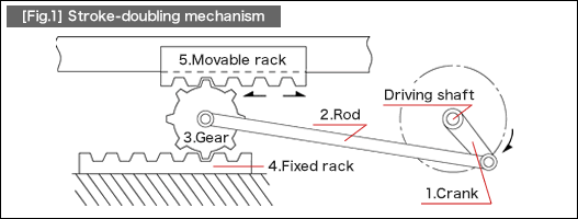
[Fig.1] is a diagram of this mechanism.

In this structure, the slider used in the standard slider crank mechanism introduced in #251 is replaced by a toothed gear. In addition, the slider guide is separated into a fixed rack and a movable rack. The crank motion on the driving shaft is transmitted to the toothed gear. Then, the stroke of rolling motion (L) over the fixed rack increases by 100% (2L) when it reaches the gear top. This stroke (2L) acts on the movable rack installed on the gear top.
(1)Application examples
The structure tends to be longer than originally intended if a pneumatic cylinder and a slide way (linear guide) are used or if a structure where ball screws are used for connecting a motor is adopted. This automation clever mechanism is an effective solution for making the fixture short and compact.
Application examples
1.Oscillating motion of a processing machine
2.Reciprocating linear motion mechanism for one-piece flow production fixture
(printing, wiping, pressuring, and others)
3.Inspection jigs
(2)Tips on selecting appropriate standard components
All of the parts shown in [Fig.1] can be assembled by using the standard components. This section explains the assembly of gears and racks.
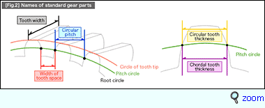
The Module value (m) in the catalog is used to determine a combination of gears and racks. The components are compatible if items with the same module value are mixed. (See the below figure.)
|
- Positioning technology
- Designing and processing
- Sensor Technology
- Automation elements technology
- Clean room technology
- Design hints
- Design tips
- Designing and Machining
- Drive mechanism design
- Hints on designing
- Linear Motion Components
- Locating Technology
- Manufacturing technology
- Motion mechanism design
- Pneumatic Drives
- Production Technology
- Technology Outlook
- General description
- Low-cost automation and materials
- Transfer LCA
- #333 Know-how on automation: Pressurized heating technology - 5: Multilayer pressurized heating process technique
- #332 Know-how on automation: Pressurized heating technology - 4: Points to remember when designing mechanism of pneumatic pressurization method
- #331 Know-how on automation: Pressurized heating technology - 3: Pneumatic pressurization method and pressure profile
- #330 Know-how on automation: Pressurized heating technology - 2: Pressurization method and pressure profile
- #329 Know-how on automation: Pressurized heating technology


