#254 Basic Elements of Automation Clever Mechanisms: Rotary-Linear Motion Conversion Mechanism 4
Rotary motion can be converted into linear motion by using a screw. This volume introduces an automation clever mechanism that allows control of linear motion in various ways by adopting different types of screw structures. "Threaded" and "tapped" screws are used as a cam in this volume.
[Fig.1] is a diagram of the automation clever mechanism where two pieces of reversing screws are assembled onto a shaft.
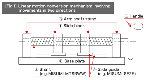
If the handle installed on the right edge is rotated, it causes a linear motion of the slide block placed on the two tapped screws that are assembled to the opposing two screws. This structure can also be applied for a double-speed mechanism, where single rotation of the handle is transformed into a movement of twice the pitch of the rotation.
Application examples
| 1. | Electric terminal positioning or scanning movement for inspection equipment | |
| 2. | Adjustment mechanism for edge positioning of jigs compatible with various products | |
| 3. | Double-speed mechanism |
[Fig.2] shown here has a different screw structure to [Fig.1].
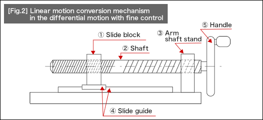
Moving the shaft connected to the handle by one pitch can create differential motion from the slide block movement. In other words, single rotation of the handle will move the shaft the distance of screw pitches towards the left side. Simultaneously, the slide block moves the distance of screw pitches in the reverse direction of the shaft movement (towards the right side). Since the relative motion of the shaft and slide block here is equal to the difference (differential motion) of these two movements, precise adjustment on the movement is possible. A fine thread screw has been adopted for the slide block parts in [Fig. 2]. However, using a screw with the same pitch as the right one can still produce the fine movement because this mechanism works by the differential motion.
Application examples
| 1. | Auxiliary positioning mechanism for inspections using a magnifying microscope or positioning work. | |
| 2. | Precision positioning mechanism | |
| 3. | Speed reducer |

- Positioning technology
- Designing and processing
- Sensor Technology
- Automation elements technology
- Clean room technology
- Design hints
- Design tips
- Designing and Machining
- Drive mechanism design
- Hints on designing
- Linear Motion Components
- Locating Technology
- Manufacturing technology
- Motion mechanism design
- Pneumatic Drives
- Production Technology
- Technology Outlook
- General description
- Low-cost automation and materials
- Transfer LCA
- #333 Know-how on automation: Pressurized heating technology - 5: Multilayer pressurized heating process technique
- #332 Know-how on automation: Pressurized heating technology - 4: Points to remember when designing mechanism of pneumatic pressurization method
- #331 Know-how on automation: Pressurized heating technology - 3: Pneumatic pressurization method and pressure profile
- #330 Know-how on automation: Pressurized heating technology - 2: Pressurization method and pressure profile
- #329 Know-how on automation: Pressurized heating technology


Please visit your Regional MISUMI website for additional information or to request our latest catalog.
Unauthorized reproduction is prohibited by all applicable laws and is subject to criminal prosecution.