#003 Installing Shafts - 1 : Variables in Execution
Installation of shafts depends on the design of the shaft holder that is constrained by the structure of the entire mechanism, requirements for ease of assembling and disassembling, and the limitation of the size of the mechanism.
(1)Reference planes of the base plate on which shafts are to be installed
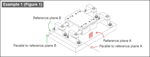
Shafts must be installed parallel to the reference planes so that the linear table can move accurately. Usually, the upper face and one end face of a shaft holder fixing plate (e.g., base plate) are used as the reference planes. (See Figure 1)

(2)Shaft holders and shape of shaft ends
Shape of shaft ends suitable for the structure of your mechanism should be selected.
In the case of Figure 1, the base plate does not have any reference for positioning, thus two shafts are made parallel by the adjusting them during their installation.
Shape of shaft ends
Select straight type shaft ends. The shafts are fixed by shaft holders, thus the shaft ends do not need special machining.
Installing the shaft holders
| 1. | Fix two shaft holders for securing the first shaft perpendicular to the face of the base plate. | |
| 2. | Put one shaft through the bushing on one side of the movable table, install it onto the shaft holder, and fix the shaft to the shaft holder. | |
| 3. | Put the other shaft through the movable table bushings, and temporarily loosely fasten the two shaft holders with fixing bolts. | |
| 4. | Slide the movable table slowly to confirm that the table moves smoothly before you tighten the fixing bolts firmly. |

Shape shaft ends
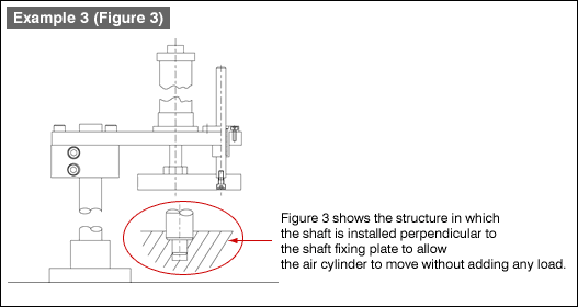
Figure 3 shows the structure in which the shaft is installed perpendicular to the shaft fixing plate to allow the air cylinder to move without adding any load.

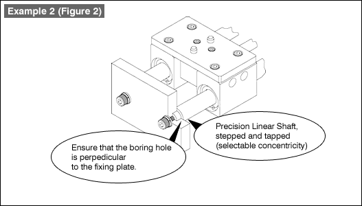
Note: In order to install two shafts perpendicular to the shaft fixing plate, shafts with stepped and tapped ends are used. Dimensional accuracy and concentricity of the shouldered section allow the shafts to be fixed at a right angle.
- Positioning technology
- Designing and processing
- Sensor Technology
- Automation elements technology
- Clean room technology
- Design hints
- Design tips
- Designing and Machining
- Drive mechanism design
- Hints on designing
- Linear Motion Components
- Locating Technology
- Manufacturing technology
- Motion mechanism design
- Pneumatic Drives
- Production Technology
- Technology Outlook
- General description
- Low-cost automation and materials
- Transfer LCA
- #333 Know-how on automation: Pressurized heating technology - 5: Multilayer pressurized heating process technique
- #332 Know-how on automation: Pressurized heating technology - 4: Points to remember when designing mechanism of pneumatic pressurization method
- #331 Know-how on automation: Pressurized heating technology - 3: Pneumatic pressurization method and pressure profile
- #330 Know-how on automation: Pressurized heating technology - 2: Pressurization method and pressure profile
- #329 Know-how on automation: Pressurized heating technology


