HOME > Low Cost Automation Tutorial > #004 Installing Shafts - 2 : Practical Examples
Low Cost Automation Tutorial
#004 Installing Shafts - 2 : Practical Examples
Category : Linear Motion Components
July24, 2009
Two cases will be introduced in terms of design features and maintainability. In case 1, the shafts are directly installed, and in case 2, the shafts are installed via shaft holder brackets.
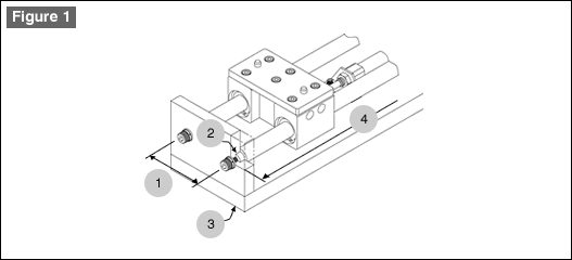
Case 1 (See Figure 1)
The structure of the shaft with retaining ring groove is as follows:
| 1. | The two bores on each of the two shaft fixing plates, through which both ends of the shafts are fixed, determine the parallelism of the two shafts. Therefore, the distance between the two bores on the shaft fixing plates should be specified with tolerance. | |
| 2. | The precision of the shaft installing bores on the two shaft fixing plates must be specified with clearance fit (H7) that is required for precision fitting with minimal rattling. | |
| 3. | Be sure to use large fixing bolts to secure the relative positions of the shaft fixing plates to the base plate. | |
| 4. | The distance between the two retaining ring grooves on the shaft ends (distance L selectable in units of one millimeter) must be slightly longer than the outer distance between the two shaft fixing plates but without allowance in the longitudinal direction of the shafts. |
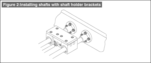
Case 2 (See Figure 2)
The structure of the shaft holder bracket is as follows:| 1. | The parallelism of the two shafts is determined by the parallelism of the shaft holder bracket fixing plates (via which both ends of shafts are fixed) and by the precision of installing intervals of the shaft holder brackets. | |
| 2. | Shaft holder brackets can be installed by tapping the shaft holder bracket fixing plates. | |
| 3. | This structure assures high rigidity as the precision flanges hold the shafts. | |
| 4. | Depending on the shape of the shaft ends on the opposite side, a variety of assembling procedures are possible. When shaft holder brackets are used for both sides, installation should be made by temporarily fixing the shafts, movable units and shaft holder brackets on the fixing plates before securing the plates on the peripheral structure. Also, be aware of the complexity of disassembling and maintenance of the shafts before starting the design of your mechanism. | |

- Positioning technology
- Designing and processing
- Sensor Technology
- Automation elements technology
- Clean room technology
- Design hints
- Design tips
- Designing and Machining
- Drive mechanism design
- Hints on designing
- Linear Motion Components
- Locating Technology
- Manufacturing technology
- Motion mechanism design
- Pneumatic Drives
- Production Technology
- Technology Outlook
- General description
- Low-cost automation and materials
- Transfer LCA
- #333 Know-how on automation: Pressurized heating technology - 5: Multilayer pressurized heating process technique
- #332 Know-how on automation: Pressurized heating technology - 4: Points to remember when designing mechanism of pneumatic pressurization method
- #331 Know-how on automation: Pressurized heating technology - 3: Pneumatic pressurization method and pressure profile
- #330 Know-how on automation: Pressurized heating technology - 2: Pressurization method and pressure profile
- #329 Know-how on automation: Pressurized heating technology


Please visit your Regional MISUMI website for additional information or to request our latest catalog.
This site is maintained by MISUMI Corporation.
Unauthorized reproduction is prohibited by all applicable laws and is subject to criminal prosecution.
Unauthorized reproduction is prohibited by all applicable laws and is subject to criminal prosecution.
Copyright © 2011 MISUMI Corporation All Rights Reserved.