HOME > Low Cost Automation Tutorial > #101 Basics of Automation Parts Machining - 2 : Notes on Designing for Part Shapes to be Hole Machined
Low Cost Automation Tutorial
#101 Basics of Automation Parts Machining - 2 : Notes on Designing for Part Shapes to be Hole Machined
Category : Designing and Machining
January20, 2012
Holes are machined by the following three methods.

For the best cost economy it offers, a) is the most general hole machining method.
Some notes on the points are introduced below to consider for the shape designs when drill machining.
Examples to be noted when drill machining.
- For drilling, the metal is cut by a rotating bit with push forces and rotational speeds.
- When drilling, the tip of the drill (Name: chisel edge) is rotating at zero speed since the center of the point has no radius.
- The function of this chisel edge is to dig into the metal to be cut and create a priming point.
- When the drill is pushed against the metal to be cut, the chisel edge can cut into the metal perpendicularly.
- However when the drill is not perpendicular, the chisel edge does not bite the metal correctly and the hole machining will not be straight.
- Therefore, the drilling surface should be designed to be perpendicular to the drill axis.
[Example-1] Machining a tapped hole on a slope

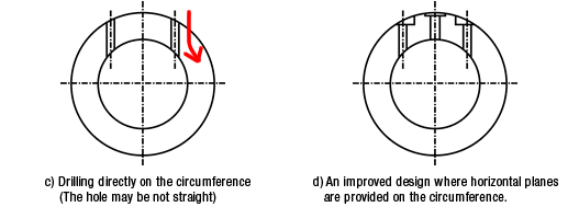
[Example-2] A case of hole machining on a circumference of a circle

- Positioning technology
- Designing and processing
- Sensor Technology
- Automation elements technology
- Clean room technology
- Design hints
- Design tips
- Designing and Machining
- Drive mechanism design
- Hints on designing
- Linear Motion Components
- Locating Technology
- Manufacturing technology
- Motion mechanism design
- Pneumatic Drives
- Production Technology
- Technology Outlook
- General description
- Low-cost automation and materials
- Transfer LCA
- #333 Know-how on automation: Pressurized heating technology - 5: Multilayer pressurized heating process technique
- #332 Know-how on automation: Pressurized heating technology - 4: Points to remember when designing mechanism of pneumatic pressurization method
- #331 Know-how on automation: Pressurized heating technology - 3: Pneumatic pressurization method and pressure profile
- #330 Know-how on automation: Pressurized heating technology - 2: Pressurization method and pressure profile
- #329 Know-how on automation: Pressurized heating technology


