#255 Basic Elements of Automation Clever Mechanisms: Rotary-Linear Motion Conversion Mechanism 5
A cam is the typical mechanical component used in the rotary-linear motion conversion mechanism. In this volume, we will look into application examples of the cam.
Cams are the excellent choice because of the following characteristics:
| 1. | Motion characteristics as speed, acceleration, and forces can be freely controlled by the output end to which the cam motion is transmitted. | |
| 2. | When combined with the link mechanism, incorporating a cam into the structure allows you to design a compact, lightweight yet highly rigid mechanism in a simple structure. | |
| 3. | Cams can shorten the overall cycle time as they can overlap and control multiple movements. | |
| 4. | Highly reliable. |
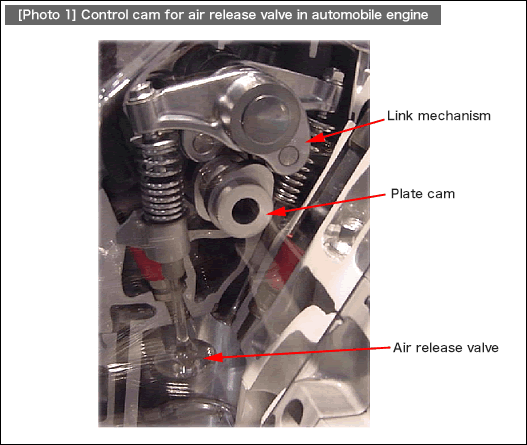
Based on these characteristics, cams are adopted in various applications including the terminal press fitting mechanism of a high-speed terminal press fitting machine, as well as the high-speed and complex timing control of an air release valve for an automobile engine. (See [Photo 1].) In the photo below, displacement of the plate cam is enlarged by the link mechanism. In order to ensure the high-speed responses, springs to prevent jumping have been installed.

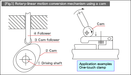
A cam introduced here as the basics of automation clever mechanisms works as a supportive element that allows for quick attachment/detachment of fixtures by transforming the linear motion displacement into forces, rather than converting rotary motion into linear motion, which was explained earlier as a superior characteristic of cams used in motion control.
In [Fig.1], the rotary-linear motion conversion mechanism using a typical plate cam and a reciprocating follower is shown left and the one-touch clamp mechanism next to it.
Application examples
•1.Clamping mechanism of one-touch lever operation system

- Positioning technology
- Designing and processing
- Sensor Technology
- Automation elements technology
- Clean room technology
- Design hints
- Design tips
- Designing and Machining
- Drive mechanism design
- Hints on designing
- Linear Motion Components
- Locating Technology
- Manufacturing technology
- Motion mechanism design
- Pneumatic Drives
- Production Technology
- Technology Outlook
- General description
- Low-cost automation and materials
- Transfer LCA
- #333 Know-how on automation: Pressurized heating technology - 5: Multilayer pressurized heating process technique
- #332 Know-how on automation: Pressurized heating technology - 4: Points to remember when designing mechanism of pneumatic pressurization method
- #331 Know-how on automation: Pressurized heating technology - 3: Pneumatic pressurization method and pressure profile
- #330 Know-how on automation: Pressurized heating technology - 2: Pressurization method and pressure profile
- #329 Know-how on automation: Pressurized heating technology


