#295 Know-how on automation: Transfer -3
General description
Based on the comparison of planned arrangement of feed rollers (a total of three (3) proposals), the features of roller transport system have been explained.This case study will help increase the practical skills to select appropriate drive systems for the required considerations for mechanical design of transfer systems.
Explanation
1)Application to mechanical design of roller transport system
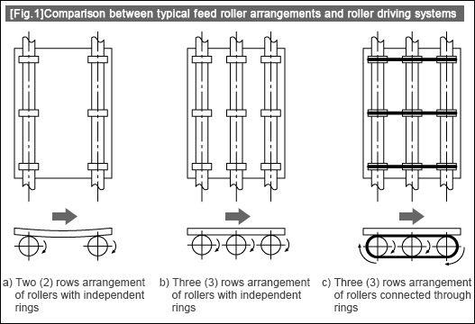
The roller transport system is configured with feed rollers and other mechanical sections. This session explains a total of three (3) plans for arrangement of feed rollers (Fig.1).
Plan A): Two (2)-rows independent arrangement of feed rollers (Fig.1-a)
・If glass substrates vary greatly in deflection or O-rings are worn partially or unevenly, poor or inconsistent contact between substrates and rollers can result, leading to possible curved transport.
・In the designing of roller materials and diameters, consideration may be given so as to make the feed rollers at the respective ends serve as main rollers and the feed rollers in the middle act as sub rollers, thereby ensuring stable transfer.
Plan B): Three (3)-rows independent arrangement of feed rollers (Fig.1-b)
・In order to minimize the effects of deflection of thin substrates in Plan A), the substrates are supported and transferred on the rollers arranged in 3 rows.
・By installing rubber-made O-rings on the outer circumference of rollers to transmit the frictional force, increased and stabilized friction coefficient and enhanced ease of maintenance are expected.
Plan C): Three (3)-rows arrangement of feed rollers connected through one ring (Fig.1-c)
・This Plan can involve the following problems: Direct susceptibility to any differences (related to friction coefficient) between the three (3) O-rings in contact with the substrates, increased parts processing cost, and/or increased person-hours for assembling and/or maintenance for stabilized tension of O-rings.
Among the 3 Plans, the Plan shown in Fig.1-b is more favorable for transfer of glass substrates of reduced thickness and weight.The next session explains the capability of transfer in a straight flow using the mechanical design based on Plan B.

- Positioning technology
- Designing and processing
- Sensor Technology
- Automation elements technology
- Clean room technology
- Design hints
- Design tips
- Designing and Machining
- Drive mechanism design
- Hints on designing
- Linear Motion Components
- Locating Technology
- Manufacturing technology
- Motion mechanism design
- Pneumatic Drives
- Production Technology
- Technology Outlook
- General description
- Low-cost automation and materials
- Transfer LCA
- #333 Know-how on automation: Pressurized heating technology - 5: Multilayer pressurized heating process technique
- #332 Know-how on automation: Pressurized heating technology - 4: Points to remember when designing mechanism of pneumatic pressurization method
- #331 Know-how on automation: Pressurized heating technology - 3: Pneumatic pressurization method and pressure profile
- #330 Know-how on automation: Pressurized heating technology - 2: Pressurization method and pressure profile
- #329 Know-how on automation: Pressurized heating technology


Please visit your Regional MISUMI website for additional information or to request our latest catalog.
Unauthorized reproduction is prohibited by all applicable laws and is subject to criminal prosecution.