#322 Know-how on automation: Designing high-precision automation devices - 3
(1)Detailed description of factors for bias error
This section tries to deepen understanding on factors and solutions for "bias errors" taking the actual measurement equipment as an example.
・Here, fluctuating factors for "bias errors" due to temperature drift are roughly divided into two groups: a) stabilizing temperature of measurement equipment, and b) thermal deformation in the mechanical components for automation devices.
a)Temperature drift in measurement equipment
b)Thermal deformation of automation devices
・This section describes a) Temperature drift in measurement equipment.
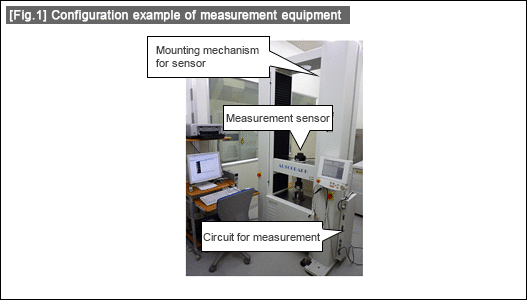
・Measurement equipment for positioning consists of three main components: "measurement sensor", "circuit for measurement", and "mounting mechanism for measurement sensor". Accuracy variation on measurement time varies by component. Universal test machine in Fig.1 consists of "measurement sensor" (load sensor), "circuit for measurement" (measuring unit for load sensor), and "mounting mechanism for measurement sensor" (gate type mechanism).

・Although a "measurement sensor" itself is designed to be insensitive (cover protection, material selection, etc.) to fluctuations in the environment, the sensors using composite structural members, such as laser beam, piezoelectric element, etc. are likely to be affected by temperature drifts.
・In the "circuit for measurement", temperature drifts in many electronic components on the circuit board cannot be avoided because the temperature in the circuit boards, etc. inside rises to a certain degree after the power on. Handling, thus, is necessary in such a way that measurement should start after the temperature rises to certain degree. The period until the temperature reaches the required level is called "warm-up time". "Warm-up time" required for measurement equipment is generally about 10 minutes.
・"Mounting mechanism for measurement sensor" is affected by temperature changes in the mechanical components. In the testing facility where accurate measurement is required, even the universal test machine in Fig.1 is also placed under the constant room temperature.
・Fig.2 shows the relationship between temperature drift in "circuit for measurement" and the "warm-up time" as the countermeasure. The straight line in figure 2 represents the ideal measurement data. The data that has the property of curved line at the start shows the case where temperature drifts. Effects of temperature drift can be avoided by starting the measurement at the point when the "warm-up time" of this curved line is past.
![[Fig. 2] Illustration of temperature drift and warm-up time as the countermeasure [Fig. 2] Illustration of temperature drift and warm-up time as the countermeasure](/tt/en/lca/d541.gif)
- Positioning technology
- Designing and processing
- Sensor Technology
- Automation elements technology
- Clean room technology
- Design hints
- Design tips
- Designing and Machining
- Drive mechanism design
- Hints on designing
- Linear Motion Components
- Locating Technology
- Manufacturing technology
- Motion mechanism design
- Pneumatic Drives
- Production Technology
- Technology Outlook
- General description
- Low-cost automation and materials
- Transfer LCA
- #333 Know-how on automation: Pressurized heating technology - 5: Multilayer pressurized heating process technique
- #332 Know-how on automation: Pressurized heating technology - 4: Points to remember when designing mechanism of pneumatic pressurization method
- #331 Know-how on automation: Pressurized heating technology - 3: Pneumatic pressurization method and pressure profile
- #330 Know-how on automation: Pressurized heating technology - 2: Pressurization method and pressure profile
- #329 Know-how on automation: Pressurized heating technology


