HOME > Low Cost Automation Tutorial > #213 Design Image Training - 29: Dimensioning in Assembly Drawing
Low Cost Automation Tutorial
#213 Design Image Training - 29: Dimensioning in Assembly Drawing
Category : Hints on designing
October 2, 2015
This section explains dimensioning in assembly drawings.
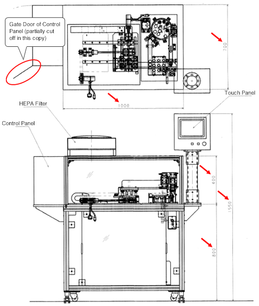
- [Fig.1] is the front view and plan view included in the entire assembly drawing of the Bingo Machine.In these views, there are five areas with their dimensions specified.
- The purpose of dimensioning in the entire assembly drawing is to provide typical dimensions of the device as well as to understand its outline dimensions used for layout information or inspection at delivery.
- Therefore, if the device includes a gate door (example: red circle part in [Fig.1]), a good drawing should include the full-width dimensions when the door is open. This way, the drawing is also useful for securing the maintenance space during the layout process.

Dimensioning in subunit assembly drawing
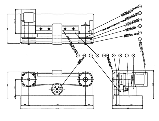
- A good assembly drawing of a subunit should include as many assembled dimensions as possible.
- Using the values of the dimensions specified in the subunit assembly drawing is extremely efficient in reviewing the part dimensions after creating the part drawing from the subunit assembly drawing.
- [Fig.2] is the assembly drawing of the Belt Driven Shuttle Unit introduced as a usage example of the standard components listed in the MISUMI FA Mechanical Standard Components Catalog.This drawing includes almost all of its external dimensions and assembled dimensions.

- Positioning technology
- Designing and processing
- Sensor Technology
- Automation elements technology
- Clean room technology
- Design hints
- Design tips
- Designing and Machining
- Drive mechanism design
- Hints on designing
- Linear Motion Components
- Locating Technology
- Manufacturing technology
- Motion mechanism design
- Pneumatic Drives
- Production Technology
- Technology Outlook
- General description
- Low-cost automation and materials
- Transfer LCA
- #333 Know-how on automation: Pressurized heating technology - 5: Multilayer pressurized heating process technique
- #332 Know-how on automation: Pressurized heating technology - 4: Points to remember when designing mechanism of pneumatic pressurization method
- #331 Know-how on automation: Pressurized heating technology - 3: Pneumatic pressurization method and pressure profile
- #330 Know-how on automation: Pressurized heating technology - 2: Pressurization method and pressure profile
- #329 Know-how on automation: Pressurized heating technology


