HOME > Low Cost Automation Tutorial > #214 Design Image Training - 30: Handling Structural Issues in Drawing Process
Low Cost Automation Tutorial
#214 Design Image Training - 30: Handling Structural Issues in Drawing Process
Category : Drive mechanism design
October16, 2015
As the structure is becoming closer to reality while making progress with the assembly drawing design, the designer may encounter an issue that the actual structure may not be the same as the conceptual design.
This section introduces some of the solutions in such cases.
- The following solutions are available if the designer encounters an issue while making progress with the design work. If it happens, the designer himself/herself must surely resolve the issue.
Issue Solutions Specific examples of the solution A structural problem occurs in the initial conceptual drawing. - Mark the area of concern and add an alternative idea in the design drawing.
- If it is not possible to come up with an alternative idea, try finding a solution while working on another drawing to buy some time.
- For [Fig.1]:
Illustrate the risk of thermal deformation for the cover and write a memo that this issue must be resolved. - If the design includes any component(s) to be concerned about, design an alternative component and procure the processed goods of the alternative component(s) in the assembly process.
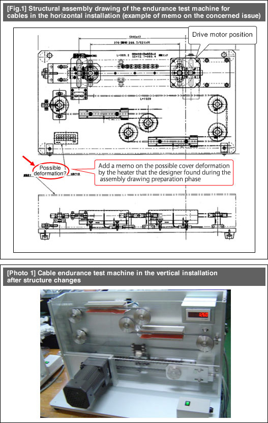
- [Fig. 1] is the assembly drawing of an endurance test machine for cables.
- A heater to increase the cable temperature is embedded in this test machine. The assembly drawing includes a description of this expected issue that the cover may be deformed by the heat generated from the heater.
- As you can see from [Photo 1], the actual test machine completed is different from the assembly drawing shown at [Fig.1].
- The assembly parts layout has been modified drastically in order to resolve the possible issue on the cover deformation. In addition, the designer has reduced the installation area of the test machine and moved the center of gravity to a lower position in order to improve the installation stability.
- The test machine was going to be installed horizontally during the [Fig.1] design process. Then, the completed structure was modified by installing the flat plate in the vertical direction. By doing so, you can achieve the followings: 1) Release the heat from the heater upward into the air; 2) Place the installation plate and the motor on the bottom to move the center of gravity to a lower position (see [Photo 1]).

- Positioning technology
- Designing and processing
- Sensor Technology
- Automation elements technology
- Clean room technology
- Design hints
- Design tips
- Designing and Machining
- Drive mechanism design
- Hints on designing
- Linear Motion Components
- Locating Technology
- Manufacturing technology
- Motion mechanism design
- Pneumatic Drives
- Production Technology
- Technology Outlook
- General description
- Low-cost automation and materials
- Transfer LCA
- #333 Know-how on automation: Pressurized heating technology - 5: Multilayer pressurized heating process technique
- #332 Know-how on automation: Pressurized heating technology - 4: Points to remember when designing mechanism of pneumatic pressurization method
- #331 Know-how on automation: Pressurized heating technology - 3: Pneumatic pressurization method and pressure profile
- #330 Know-how on automation: Pressurized heating technology - 2: Pressurization method and pressure profile
- #329 Know-how on automation: Pressurized heating technology


