HOME > Low Cost Automation Tutorial > #218 Design Image Training - 34: Designing a Pneumatically Driven System
Low Cost Automation Tutorial
#218 Design Image Training - 34: Designing a Pneumatically Driven System
Category : Drive mechanism design
December11, 2015
As mechanical systems require their mechanism drawings, it is necessary to prepare a design drawing for pneumatically/hydraulically driven systems. This section explains the design drawing of a pneumatically driven system.
- The basic rules of mechanical design are defined in the followings: JISB0001 Technical drawings for mechanical engineering, JISB0002-1, 2, 3 Technical drawings - Screw threads and threaded parts, and JISB0401-2 ISO system of limits and fits.
- In the same manner, the basic rules of pneumatically/hydraulically driven systems are defined in the followings: JISB0125-1: Fluid power systems and components - Graphic symbols and circuit diagrams - Part 1: Graphic symbols, JISB0125-2: Fluid power systems and components - Graphic symbols and circuit diagrams - Part 2: Circuit diagrams, and JISB0142: Fluid power systems and components - Vocabulary.
- In the basic rules of mechanical design, the following design rules have been determined: (1) type and thickness of a line and (2) simplified notation system of each mechanical component (machine element), such as springs, screws, and shafts. In the process of designing a pneumatically driven system as well, the followings have been defined: (1) type and thickness of a line and (2) simplified notation system of parts comprising of each pneumatic system (refer to Vol.30 and 31).
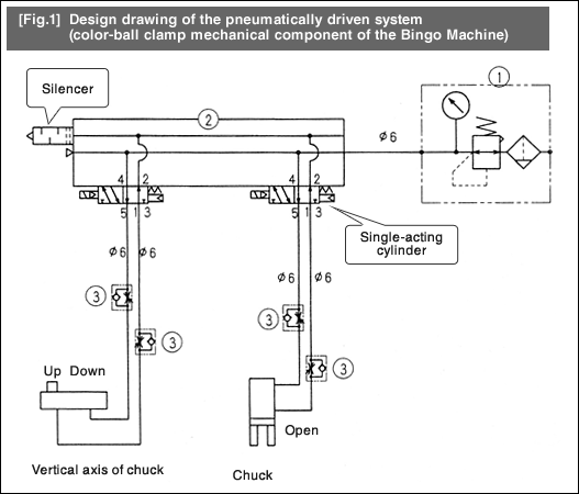
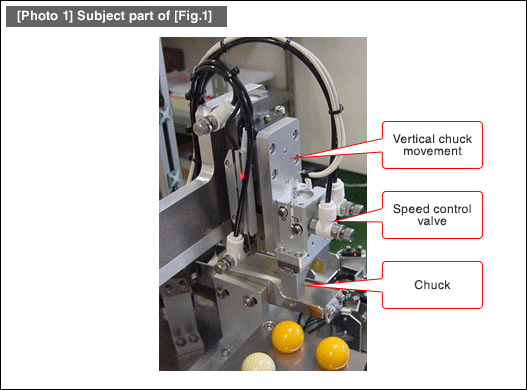
- [Fig.1] is an example of a design drawing on a pneumatically driven system installed in the color-ball clamp mechanical component of the Bingo Machine. The part number (1) is a filter regulator, (2) is an accumulator, and (3) is a speed control valve. The other components include a single-acting cylinder and a silencer.
- Since this design drawing includes parts specifications, the drawing also illustrates components, specifications, piping layout, open/close status of the chuck parts along with the positional relationship of the vertical chuck axis.


- Positioning technology
- Designing and processing
- Sensor Technology
- Automation elements technology
- Clean room technology
- Design hints
- Design tips
- Designing and Machining
- Drive mechanism design
- Hints on designing
- Linear Motion Components
- Locating Technology
- Manufacturing technology
- Motion mechanism design
- Pneumatic Drives
- Production Technology
- Technology Outlook
- General description
- Low-cost automation and materials
- Transfer LCA
- #333 Know-how on automation: Pressurized heating technology - 5: Multilayer pressurized heating process technique
- #332 Know-how on automation: Pressurized heating technology - 4: Points to remember when designing mechanism of pneumatic pressurization method
- #331 Know-how on automation: Pressurized heating technology - 3: Pneumatic pressurization method and pressure profile
- #330 Know-how on automation: Pressurized heating technology - 2: Pressurization method and pressure profile
- #329 Know-how on automation: Pressurized heating technology


