February 2013 Archives

#142 Two-Stage Ejecting Structure

| No Comments | No TrackBacks

The two-stage ejecting structure is a structure in which it is possible to carry out the ejecting operation twice at the time of ejecting the molded article from the core.
Although ejection is done only once in the usual injection mold, since in the case of the two-stage ejecting structure it is possible inside the mold to carry out ejection two times with a time gap between them, this is a mechanism that is very convenient in cases in which the molded item cannot be taken out the mold with only one ejecting operation.

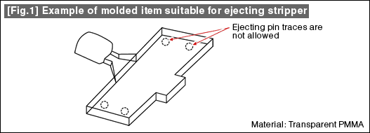
For example, in the case of the stripper plate ejecting structure such as that shown in Fig. 1, since the shape of the molded item is engraved on the stripper plate, it becomes difficult for the molded item to fall freely.

Fig. 1

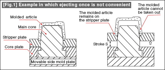
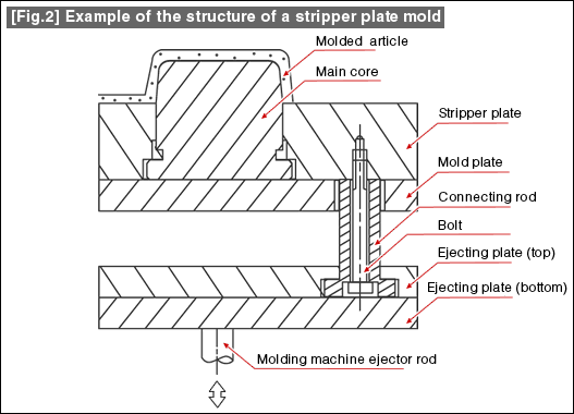
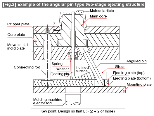
In view of this, if a two-stage ejecting structure as shown in Fig. 2 is used, it is easily possible to make the molded article fall freely.

Fig. 2

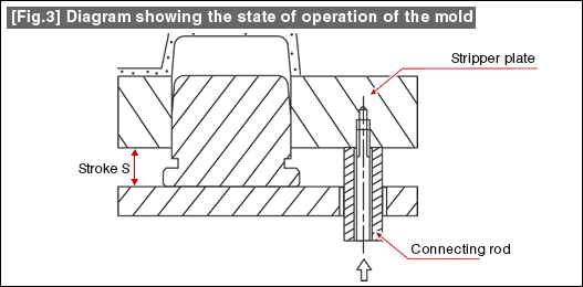
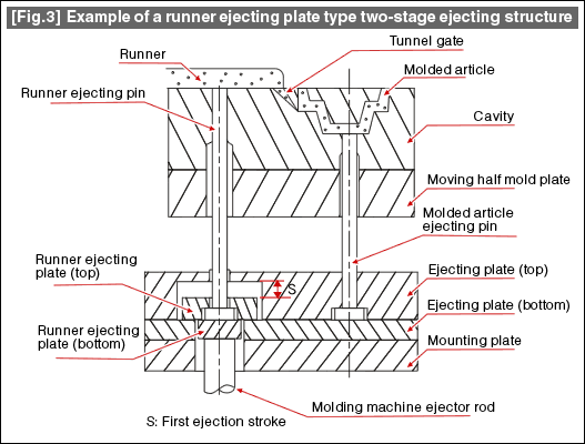
On the other hand, in the structure shown in Fig. 3, a technique has been used in which a runner ejecting plate is provided within the ejector plate thereby making only the runner to be ejected earlier than the molded item. This has the effects of improving the gate cutting ability of the tunnel gate and of reducing the cutting scrap.

Fig. 3

Apart from this, it is also possible to carry out two-stage ejection using other mechanisms. This will be a useful hint for solving problems when techniques have to be devised for the molded article ejection, runner, cutting of the gate, etc.

#141 Ejecting Stripper Plate Structure

| No Comments | No TrackBacks

The ejecting stripper structure is a structure that is used when there should be no traces of the ejector pin on the molded item.
This is used for transparent optical components made of acrylic or polycarbonate, etc., such as that shown in Fig. 1.

Fig. 1

Fig. 2 shows an actual example of the ejecting stripper structure

Fig. 2

Firstly, the main core that forms the molded artilce is fixed to the moving half mold plate using bolts, etc.
The stripper plate is placed so that it envelopes the side surface of the main core, the stripper plate is further connected to the ejector plate via a connecting rod.
In other words, when the ejector plate moves forward, even the connecting rod moves forward along with it, thereby causing the stripper plate to move forward and ejecting the molded article.

As the ejector plate returns, the stripper plate also returns to the original position.

Fig. 3

At the time of carrying out the basic design of the stripper plate structure, while it is of course necessary to prepare properly the drawing of the operating states, in addition it is very important for smooth operation to take measures such as managing the clearance between the stripper plate and the main core, tapered escape, etc.

In addition, adoption of a guide system, selection of the steel material for the stripper plate, heat treatment, etc., also become very important factors.

Fig. 4

#140 Maraging Steel

| No Comments | No TrackBacks

Maraging steel is one type of special steel used for the for plastic injection mold.
Usually, when quenching and heat treating special steels, although the solidification is done by sudden cooling from a temperature higher than the A1 transformation point (723°C) after obtaining the martensite structure, considerably large residual stresses remain in the material due to sudden cooling, and also there will be dimensional deformations. The maraging a type of steel in which the steel is hardened without taking such risks.

The following typical types are present maraging steels.

1) SUS630 type
2) Maraging steel
3) Non-magnetic steel

The principles by which the maraging steel becomes hard is that, the steel is supplied in the soft state after processing in a method called solution heat treatment. Next, after the material is machined into the component shapes such as the cavity or the core, etc., it is heated and left to cool. When this is done, a phenomenon called age hardening occurs, and the hardness of the steel increases naturally. In the age hardening process, compositions called intermetallic compounds are precipitated, and this increases the hardness.

Since heat treatment is simpler than quenched and annealed steel, it is also easy to stabilize the dimensions, and maraging steel is a useful item depending on the application.

The appropriate temperature of age hardening depends on the type of steel, and the optimum processing is selected following the respective guidelines.

The features of the different steel materials are given below.

1) SUS630 type

This steel is obtained by modifying the stainless steel SUS 630. A steel material with a hardness in the range of 35 to 40 HRC is supplied, and very often it would already have been age hardened. Its resistance to corrosion is high and is suitable for the die steels of plastics having high corroding property.

2) Maraging steel

The specularity of this steel is very good. This is used very frequently for the cavities of optical components, or lens cavities. This material has both high hardness and high strength, and also has toughness. This steel is used also for thin core pins and long and thin components.

3) Non-magnetic steel

This is a steel does not stick to a magnet and is used for plastic magnets. Since a magnet has a high hardness and wears out the steel, a high hardness is required in the steel. By carrying out solution hardening, the hardness increases and it is possible to obtain a steel having non-magnetic properties.

While in the last lesson we have explained the method of determining the external dimensions of a cavity (fixed side inserts), from this lesson onwards we explain the actual calculation of the strength of the thickness of the side wall of a cavity.

This time we shall take the example of calculating the side wall thickness of a rectangular cavity whose bottom surface is parted.

The shape of the cavity in this example is shown in Fig.1.

Fig.1

The thickness h of the side wall in Fig. 1 can be obtained using the following equation.

Here,
 h:Thickness of the cavity wall (mm),
 p:Cavity internal pressure (kgf/cm2),
 l:Inside length of the cavity (mm),
 a:Height of the side wall receiving the cavity internal pressure p (mm),
 b:Height of the cavity (mm),
 E:Modulus of elasticity (Young's modulus) (kgf/cm2)(kgf/cm2),
 σmax:Maximum permissible strain.(mm)

Calculate the values of each of the above variables according to the units within parentheses ().

The internal pressure p of the cavity takes on values in the range of 200 to 600 kgf/cm2.樹The value of p varies depending on the plastic and the molding conditions. For example, the value will be about 400 kgf/cm2in the case of ABS plastic, and will be about 600 kgf/cm2the case of PC plastic.

 l is the length of the periphery of the cavity,
 a is the depth of the periphery of the cavity, and
 b is the height of the cavity,
 E is the modulus of elasticity of the steel material of the cavity.
 See the data in some back numbers for the value.

σmax is the maximum permissible strain of the side wall. A value of 0.01 to 0.02 mm is appropriate.

The data substituted in the equation for calculation should be determined considering the molding conditions or the type of steel, etc.

In the next lesson, we will carry out actual calculations for an example.

About this Archive

This page is an archive of entries from February 2013 listed from newest to oldest.

January 2013 is the previous archive.

Find recent content on the main index or look in the archives to find all content.