October 2009 Archives

#017 Calculation of the Deflection of the Moving half Cavity Plate

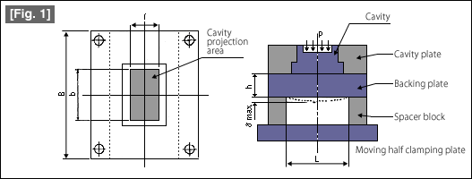
Do you have the experience of flash generated on the periphery of the parting surface of the molded product, or the height dimension of the molded product near the sprue becoming higher? The shape of the moving half cavity plate that is the basis of calculations is shown in Fig. 1.
image

The maximum deflection δmax occurs along the center line of the cavity plate. The equation for calculating the deflection is as follows.

image

B: Width of cavity plate (mm)b: Width (mm) of the part receiving the cavity injection pressure p
L: Spacing (mm) on the inside of the spacer blockp: Cavity internal injection pressure (kgf/cm3)
h: Thickness of the backing plate (mm)E: modulus of longitudinal elasticity (Young's modulus) of the material (kgf/cm2)
I: Length (mm) of the part receiving the cavity internal injection pressure pσmax: Maximum deflection (mm) of the backing plate.

The important data for E (modulus of longitudinal elasticity ) of the mold plate and p (cavity internal injection pressure) are given below.

Type of cavity plateValue of E
MaterialE(kgf/cm2)
S50C210×104
Pre-hardened steel
(SCM440 series)
230×104
Ultra duralumin73×104
cavity internal injection pressure(kgf/cm2)
Lower injection pressure200〜400
Higher injection pressure400〜600

The above equation for calculating the deflection is one for carrying out an approximate calculation. In actuality, since the pocket hole of the slide core and the holes for ejector pins have been formed in the cavity plate, and even the shape of the cavity is not uniform, it can be said that carrying out an accurate calculation of the deflection is actually very difficult. Therefore, the realistic method is to carry out the basic calculation using the approximate equation, and to correct the result to be on the safer side, or to consider factoring in a margin.
#016 How is the Rigidity of a Mold Increased?

A plastic injection mold is subjected to high internal pressure at the time of filling the molten plastic, and also, it is subjected to high compression stress at the time of clamping the mold. In addition, if the mold becomes large, it can also be subjected to a bending stress due to its own weight. In order to make sure that the mold does not get deformed or broken due to the external stresses or stresses due to its own weight, it is necessary to strengthen the rigidity of the mold.

Here, let us understand from the basics what rigidity is.

Rigidity is the resistance to deformation when subjected to a load. The modulus of longitudinal elasticity E and the modulus of transverse elasticity G of the material affect the rigidity. A material for which the value of E or G is large can be said to have a high rigidity. In other words, it exhibits strong resistance to bending or twisting. In more easy to understand terms, the material is difficult to bend, and also has a very small deflection.

For example, while the value of E for SCM440 series pre-hardened steel is 203  104 (kgf/cm2) but the value of E for SKD11 (cold rolled die steel) is 210  104 (kgf/cm2), it can be said that SKD11 is more rigid.

Explaining in more detailed terms, rigidity can be "bending rigidity" or "twisting rigidity". "Bending rigidity" is particularly more important in the case of the molds for plastic injection molding.

Bending rigidity (flexural rigidity) indicates the resistance to bending due to a bending load. In general, the bending rigidity is expressed by "E  I". (I is moment of inertia of area.For details, see the previous course.) In order to increase the bending rigidity, it is necessary to make the product E  I large. In other words, selecting a material with a large value of the modulus of longitudinal elasticity E and also adopting a cross-sectional shape that makes the moment of inertia of area I large results in making the bending rigidity high. If the structure has a high bending rigidity, even the deflection becomes small and it is also possible to resist breakage due to bending deformations.

#015 Section Modulus of Mold Components

The section modulus of mold components which is very important for predicting the bending stress is explained here.

At the time of calculating the strength against deformation or bending of a mold for plastic injection molding, the term "section modulus" appears very frequently. Let us understand how the "section modulus " is similar to the "moment of inertia of area" so as to carry out the mechanical calculations while understanding it more accurately.

The "section modulus " is a numerical value that is determined by the cross-sectional shape of the part. In that sense, it is similar to "moment of inertia of area ".

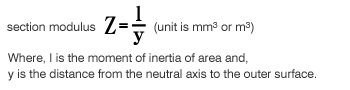
The "section modulus " varies depending only on the cross-sectional shape of the part. Therefore, it has no relationship whatsoever with the material of the part. For example, if the cross-sectional shape is the same, the value of the "section modulus " will be the same irrespective of whether the material is non-heat treated steel, tempered steel, or even wood. The definition of section modulus according to mechanics is as follows. A "section modulus is the value of the "moment of inertia of area" related to the neutral axis of the cross-section of a beam multiplied by the distance from the neutral axis to the outer surface". Therefore, the relationship between the section modulus Z and the moment of inertia of area I is as expressed by the following equation.

image

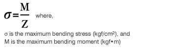
The symbol Z is used customarily for the section modulus. In general, as the section modulus becomes larger, the strength against bending also becomes larger. Regarding bending, the maximum bending stress σ acting on the outer surface of the part can be calculated using the following equation.

image

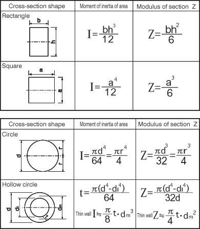
If the cross-sectional shape is rectangular or circular, the basic equation for calculation becomes clear as is shown in Table 1.

#014 Moment of Inertia of of areaMold Components

The moment of inertia of areamold components which is important for forecasting bending is explained below.

At the time of carrying out the strength calculations of a mold for plastic injection molding, the term "moment of inertia of area" appears very frequently. Let us understand again what "moment of inertia of area" is so that it is possible to progress while accurately understanding the calculation mechanics. Moment of inertia of areais a value that is identified by the cross-sectional shape of the part. This is used frequently for estimating the amount of deflection due to the bending moment or injection pressure. The moment of inertia of area changes depending only on the cross-sectional shape of a part. Therefore, it has no relationship with the material. For example, if the cross-sectional shape is the same, the value of the moment of inertia of area of areais the same whether the material is a non-heat treated steel, tempered steel, or even wood. The definition of moment of inertia of area according to mechanics is as follows. "When a cross-section is divided into an infinite number of differential areas dA and the distance from one axis X is a taken as Y, the moment of inertia of area is the sum over the entire area the product of the differential area and the square of the distance".

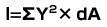
This can be expressed in the form of an equation as follows.

Cross-section second order moment is -


(unit is mm4or m4

The moment of inertia of aarea is usually represented by the symbol I as a matter of custom. In general, the strength against bending becomes larger as the moment of inertia of aarea becomes larger. If the cross-sectional shape is rectangular or circular, the basic equation for calculation becomes clear as is shown in Table 1.

Table 1

About this Archive

This page is an archive of entries from October 2009 listed from newest to oldest.

September 2009 is the previous archive.

November 2009 is the next archive.

Find recent content on the main index or look in the archives to find all content.