August 2015 Archives

#214 Heat-Saving Measures - Boiler Management -3

| No Comments | No TrackBacks

(3) Boiler combustion management

As explained in the previous session, boilers have to go through a pre-purge and a post-purge cycle before and after ignition in order to purge unburned gas from the furnace for safety purposes. During both of these purge cycles, the air blower feeds air to red-hot refractory materials in the furnace. Significant heat loss occurs during this cooling process.
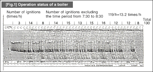
[Fig.1] shows the boiler operating status surveyed at a plant. The figure below is a timeline showing the electric current consumption by a boiler.
Figure

As is obvious from the figure, the number of ignitions per hour is three before commencing the daily operation, but has increased to 13 during the operation period on average, which is equivalent to approximately one ignition every five minutes.
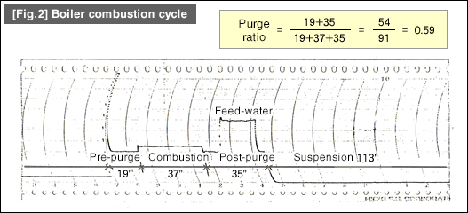
[Fig.2] show the result of more detailed operation status by speeding up the electric current recorder.
Figure

As we can see in the figure, the combustion period is 37 seconds while the purge period is 54 seconds in total, consisting of 19 seconds of pre-purge and 35 seconds of post-purge period. Based on this, the purge ratio is calculated as 54/(54+37) = 59%. This means that the period of cooling of the boiler is longer than the combustion period. In such situations, we are disposing of a large portion of fuel energy into the air. To address this inefficiency, it is necessary to reduce the number of ignitions as well as the purge period.

#213 Heat-Saving Measures - Boiler Management -2

| No Comments | No TrackBacks

(2) Boiler combustion cycle

Boiler systems use gaseous fuel such as propane and town gas as well as liquid fuel, including kerosene and fuel oil A.
All of these are flammable at a relatively low ignition temperature and considered as hazardous substances. Therefore, adopting a safe combustion method is the top priority for these fuels.
This is referred to as the combustion cycle of boilers, which must be operated under the applicable laws and regulations.
We will now take a look at the combustion system of a boiler.
[Fig.1] shows the flow sheet of the water-supply and combustion system of a boiler.

[Fig.1]

As you can see in the figure, the boiler combustion is controlled by the pressure switch (PS).
When the steam pressure falls below the preset pressure level, the pressure switch turns on and activates the burner. As the fuel starts burning, the steam pressure increases.
When the steam pressure reaches the preset level, the pressure switch turns off and fuel burning stops.
At this time, the burner operates in the time cycle shown in [Fig.2].
As soon as the pressure switch turns on, the air blower starts rotating and feeding secondary air.
After the pre-purge period, the spark period starts. In this cycle, the fuel valve opens and the pump sprays the fuel into the burner. Then, a spark occurs and ignites the fuel.
Once it has been verified that the furnace lights up inside, the spark stops.
When the pressure switch has detected the fire extinguishing pressure, the hydraulic valve closes to extinguish fire. Even after the fire goes out, the air blower continues to feed air during the post-purge period.

[Fig.2]

The purge period provided prior to and after the combustion cycle ensures the safe operation by removing (purging) unburned gas that may still be inside the furnace.
Thus, frequently repeating the combustion cycling increases the purge ratio and heat loss.

月別 Archives

Pages

Powered by Movable Type 6.0.3

About this Archive

This page is an archive of entries from August 2015 listed from newest to oldest.

July 2015 is the previous archive.

September 2015 is the next archive.

Find recent content on the main index or look in the archives to find all content.