January 2016 Archives

#224 Plating Thickness Measurement by Magnetic Method

| No Comments | No TrackBacks

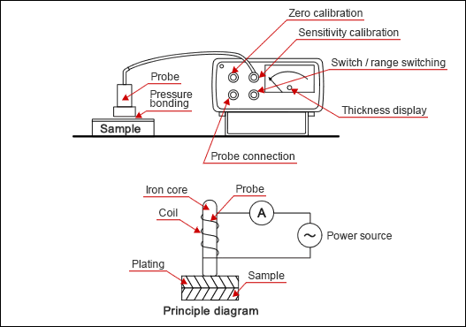
(1) Measurement principle

Apply an alternating current to the probe with a winded coil around the iron core. Place this probe onto the sample surface. The plating thickness is determined by measuring changes in the magnetic resistance of the magnetic flux that runs through the plating surface and basis metal. Because this method uses lines of magnetic force, it is designed to measure the plating thickness of non-magnetic metal on magnetic basis metal.
In general, this method is used for measuring zinc plating, chrome plating, copper plating, tin plating, and solder plating on an iron and steel substrate.
image

(2) Operation

 1. The basic operation is same as measurements by an eddy current. Prepare a substrate (made of the same materials) in the same shape as the plating sample (plate, round bar, pipe, etc.) as well as a standard sample with a known thickness.
 2. Keep the surface roughness consistent with that of the sample since it affects the measurement accuracy.
 3. Place the probe on the substrate. Then, set the indicator pointer to zero (zero calibration).
 4. Next, set the standard sample onto the substrate. Place the probe and calibrate the indicator pointer according to the standard sample thickness (sensitivity calibration). Repeat steps 3 and 4 three to four times.
 5. Measure the unknown sample under the same conditions that were applied to calibration. Measure the same area at least three times. Exclude any abnormal values and compute the average.

(3) Precaution

Please note that the following factors are known to affect the measurement accuracy:
1. Plating thickness; 2. Magnetic property of basis metal; 3. Thickness and shape of basis metal; 4. Surface roughness; 5. Edge effect.
#223 Plating Thickness Measurement by Eddy Current

| No Comments | No TrackBacks

(1)Measurement principle

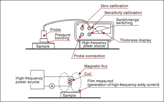
When you apply a high-frequency current to the coiled probe and place the probe against the plating surface, a high-frequency eddy current will be generated in the plating surface area. Determine the plating thickness by measuring this eddy current.

(2)Operation

Figure

1. Prepare a substrate in the same shape as the plating sample as well as a standard sample with the known thickness.
2. The surface roughness of the substrate must be same as that of a plating sample.
3. Place the probe on the substrate. Then, set the thickness indicator scale to zero (zero calibration).
4. Next, set the standard sample onto the substrate. Place the probe and calibrate the indicator scale according to the standard sample thickness (sensitivity calibration).
5. Repeat steps 3 and 4 three times (these steps are referred to as calibration). After improving the reproducibility, start the measurement.

(3)Operational precaution

1. Note that a high-frequency eddy current fluctuates considerably according to plating/basis metal properties, including electric conductivity, thickness, shape, and surface conditions.
2. Without a sufficient difference in electric conductivity between the substrate and plating, the measurement fails or accuracy is significantly reduced.
3. Perform a calibration at every measurement. The item used for calibration must be made of the same materials, in the same shape, and have the same surface conditions as the measurement sample. The calibration will not be accurate if the shape of the sample, such as plate and round bar, is different, even if they are made of the same materials.
4. Factors that could affect the measurement accuracy include the following: plating thickness, magnetic property of basis metal, shape/thickness of basis metal, surface roughness, and edge effect.

月別 Archives

Pages

Powered by Movable Type 6.0.3

About this Archive

This page is an archive of entries from January 2016 listed from newest to oldest.

December 2015 is the previous archive.

February 2016 is the next archive.

Find recent content on the main index or look in the archives to find all content.