December 2009 Archives

#024 Basics of Blanking Work (14) Finishing Blanking Work

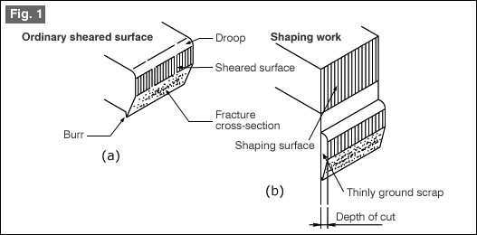
Finishing blanking work is the blanking work used for obtaining a smooth cutting cross-section surface. In the case of finishing blanking work, the clearance is made almost zero. In addition, the cutting edges of punches and dies are rounded so as to delay the generation of facture surfaces, thereby preparing smooth cut end surface.

At the time of blanking work, the cutting edge of the die is rounded as shown in [Fig. 1]. In the case of hole punching work, on the other hand, the cutting edge of the punch is rounded.

Although basically rounding is done at the cutting edge, chamfering is also permissible. It is sufficient if the working force is distributed thereby delaying the generation of fracture surfaces. The key factors here are the clearance and blunting the cutting edge (by rounding or chamfering).

[Fig. 1] Blanking work

The size of rounding is about 0.2mm to 1.0mm rounding radius. When the rounding increased, although the appearance of fracture surface is delayed and a smooth cut end surface is obtained, but there will be more droop, curve, and burrs. Therefore, it is necessary to limit the rounding (chamfering) of the cutting edge to the minimum required amount. The relationship between rounding of the cutting edge and curve is almost a straight line relationship. When the rounding radius is changed from 0.5mm to 1.0mm, the curvature becomes almost twice larger. The stripping force increases as the rounding radius becomes smaller.

#023 Basics of Blanking Work (13) Shaping Work

In ordinary blanking work the cut end surface will be like that shown in Fig. 1(a). Some times it is required that this surface is a clean sheared surface (contour shape, or hole, or part of a shape). At such times, the cut end surface is cut slightly and finished in to a clean surface as shown in Fig. 1(b). This method of working is called "Shaping work.

Fig. 1

The important item in shaping work is the size of the depth of cut shown in Fig. 1 (b). The size of the depth of cut that can be removed by one operation is about 5% to 10% of the material plate thickness. For example, a rough guide to the value of this depth of cut is about 5% in the case of soft steel, 8% to 10% in the case of hard steel, and about 10% in the case of brass. When one shaping work is not sufficient, a second or a third shaping may be done.

The direction of shaping can be the upright placement method shown in Fig. 2(a) or the inclined placement method shown in Fig. 2(b).

Fig. 2 Direction of shaping

In the case of the upright placement method, the contact between the product and the die is uniform and the balance is good. In the inclined placement method, since the contact is made on the side of the fracture surface, the contact is unstable and there will be fluctuations in the way the grinding is done. Since shaping work is done in the next process step after the blanking operation is made, it basically increases the number of process steps. Further, even positioning is difficult. In addition, the problem in shaping is that the thinly ground scrap gets adhered to the die because of oil, etc., and is difficult to clean off, and hence it can cause scratches to be made on the product. In this manner, although this is a very well known process, it is used only rarely. Although this process step is included in progressive cutting works, if any mistake is made in the handling of the scrap, it can cause scratches on the products thereby causing the products to be discarded. When carrying out shaping operation in progressive blanking work, measures should be taken to make this scrap join with the scrap of ordinary blanking and remove them together.

#022 Basics of Blanking Work (12) Outer Cutting Work - 6: Pilot

In outer cutting work, the cutting is done by moving (feeding) the material by the feed length (the feed pitch) using the side cut or a feeding device. At this time, any fluctuations in the feed pitch will have effect on the product. "Pilot" is used for the purpose of correcting the feed error immediately before carrying out the cutting.

A pilot is basically a round hole, and the error is corrected by inserting a shaft with a pointed tip (a pilot punch) inside this hole. There are two methods of using the hole. The method shown in Fig. 1 is one in which a hole in the product is directly used for correction, and this method is called a direct pilot. Since a hole in the product is used, the shape will be one without any wastage. The drawback of this method is that the hole used for the pilot may get deformed. Care should be taken about this when the material is a soft material such as copper or pure aluminum, etc.

Fig. 1 Direct pilot

In order to avoid this problem, the form shown in Fig. 2 is one in which a special hole for the pilot is formed in the part that becomes scrap. This is called an indirect pilot. It is possible to determine freely the position and size of the pilot hole. A pilot punch is always inserted into the hole for the pilot immediately after the hole has been punched. If possible, if the pilot is inserted several times in succession, it is possible to reduce the load on each punch. There is a relationship between the diameter of the pilot hole and the diameter of the pilot punch. Although the positioning can be done most accurately when the pilot hole diameter is equal to the pilot punch diameter, the material will be picked up when the pilot punch is coming out of the hole.

Fig. 2 Indirect pilot

Therefore, the relationship shown in Fig. 3 is used, that is, pilot hole diameter (D) is made greater than the pilot punch diameter (d). If the cut material plate thickness is assumed to be about 1mm, the difference between the two diameters should be about 0.02 when cutting high precision products, and about 0.04 in the case of ordinary precision products. This value is made small when the plate thickness of the material to be worked becomes smaller and is increased when the plate thickness increases. Fig. 3 Relationship between the pilot diameter and pilot hole

Figure 4 shows the amount of correction made by the pilot. The feed pitch error is corrected by the tip part of the pilot. The formed shape of the tip part can be the shape of a bullet or the shape of a taper. For the amount of correction, it is better that the diameter of the pilot punch is large, but it is important to achieve a balance with the plate thickness of the material. Assuming a plate thickness of 1mm and a pilot diameter of about 8mm, the amount of correction is in the range of about 0.3 to 0.5. If the amount of correction is large, the pilot punch gets worn out faster. Fig. 4 Amount of correction by the pilot

#021 Basics of Blanking Work (11) Outer Cutting Work - 5: Side Cut

The outer cutting work is also called cut and carry work. This is because the cutting is done after feeding the material by the feed length (feed pitch). If the feed pitch is not accurate, the cut shape will have fluctuations, and the product may not be acceptable at all in some cases. Side cut is used for the purpose of stabilizing the feed pitch.

Figure 1 shows the method of using a side cut. The edge of the material is notched by the feed pitch, and the feed length is determined by making the notched part butt against a stopper. A guideline for the width of the notch is a minimum value of about 1.5 to 2 times the material plate thickness.

[Fig. 1] Outer cutting work and side cut

If the cut is merely in the shape of the letter L, a projection shaped matching part is generated as is shown in Fig. 2. If this happens, this can lead to problems because it can get caught in the material guide. Further, a side cut also has a shape that can cause rising of chaff. In particular, the simple L-shaped cut can easily cause rising of chaff.

[Fig. 2] Projection part of a side cut

As a countermeasure, the shape of the side cut is made complex thereby solving the problems of projection shaped matching parts and rising of chaff. Fig. 3 is a shape that anybody will try at first. Although it appears as if the problems will get solved, this is not a sufficient countermeasure. Of course, this can also cause the generation of abnormality in the matching parts.

[Fig. 3] Side cut projection part counter measure (1)

Figure 4 shows a shape that has solved the problems. This can be used against both matching parts and rising of chaff. Slightly wider side cut will be necessary.

[Fig. 4] Projection part of side cut

Only the basic details have been given here. In actuality, for the sake of further countermeasures against rising of chaff, very often the shape is made complex. Cutting by combining a side cut and a part of the outer shape of the product is also done. When the feed pitch is determined only by a side cut, although the side cut punch is made the same as the feed pitch, when a pilot is used for positioning, it is common to make the length of the side cut more than the feed pitch. In this case, the material is made to be fed a little excessively and is returned slightly using the pilot.

About this Archive

This page is an archive of entries from December 2009 listed from newest to oldest.

November 2009 is the previous archive.

January 2010 is the next archive.

Find recent content on the main index or look in the archives to find all content.