November 2009 Archives

#020 Basics of Blanking Work (10) Outer Cutting Work - 4: Matching

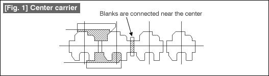
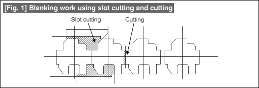
The cutting and joining parts indicated by (a) to (d) in Fig. 1 are generated when the outer contour shape is prepared by outer cutting operation in progressive cutting, etc. The cutting and joining parts are the shape parts prepared due to the intersection of two punches. Such parts are generally called "Matching parts".

Fig. 1 Outer cutting work and matching parts

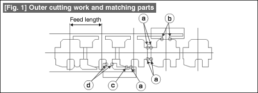
The part indicated by (a) in Fig. 1 is the matching part where there is a 90º right angle intersection. The part indicated by (b) is a matching part that is generated in a straight line part. The part indicated by (c) is a matching part in an angular part and that indicated by (d) is a matching part in a rounded part. These four patterns are the basic matching parts. The 90º right angle intersection matching part does not need any special measures, and can be said to be an ideal matching condition.

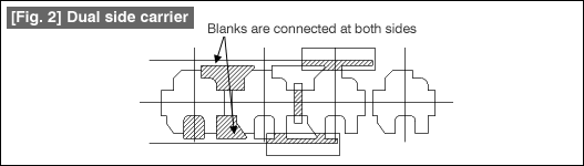
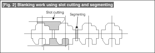
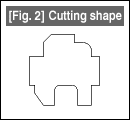
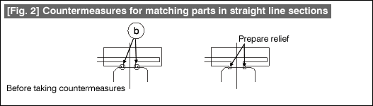
Unless countermeasures are taken for the straight line section matching part of Fig. 2, it will lead to generation of steps or burrs. This is because the same part is cut twice by a punch. The action to be taken is to provide a relief at the part which is cut twice, thereby making the cut parts intersect each other. In the external appearance of the formed product, the matching parts will remain as depressions. Since the matching parts have some effect in this manner in the external appearance, care should be taken so that matching parts are not created in parts where they can affect the functions of the product.

Fig. 2 Countermeasures for matching parts in straight line sections

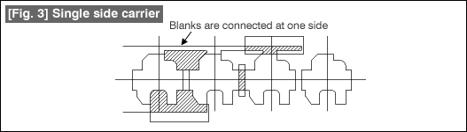
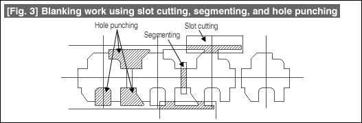
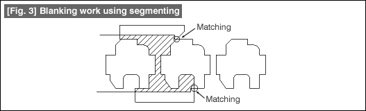
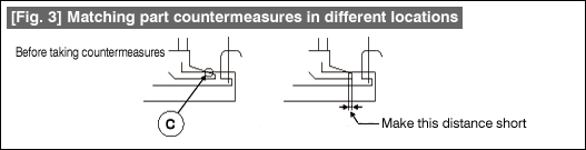
In the matching parts in angular sections shown in Fig. 3, it is easy for plucking type of burrs to be generated. Design a cutting edge shape (cut punch) in which the extension part of the inclined line is as short as possible.

Fig. 3 Matching part countermeasures in different locations

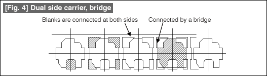
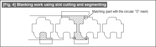
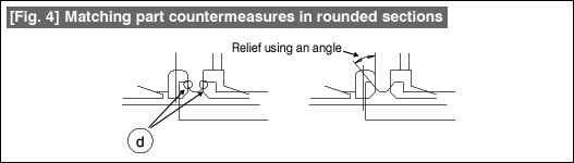
In the matching part in a rounded section shown in Fig. 4, is the rounding shape is attempted to be made correctly, the same condition as in a matching part in a straight line section occurs. Therefore, the cut punch should be designed so that a tangent is drawn from the rounded section and so that it intersects the straight line part at an angle.

Fig. 4 Matching part countermeasures in rounded sections

In outer cutting work, although various measures can be taken because the cut punch can be prepared freely, the drawback is the generation of matching parts. If any mistake is made in the countermeasures against matching parts, it can lead to the generation abnormalities such as burrs. When such a thing has happened, it is very difficult to take corrective countermeasures. Therefore, it is very important to think of countermeasures at the time of designing the cut punch so that problems do not occur and then carry out the design.

#019 Basics of Blanking Work (9) Outer Cutting Work - 3: Method for Connecting Blanks

In outer cutting work, the shape of an outer contour is cut mainly using slot cutting. Because of this, as is shown in Fig. 1, it is natural for neighboring blanks to be connected at the middle part of the blanks. This form is called the "center carrier" form. The carrier is the part where the material is connected for feeding the material. It is necessary that the carrier has enough strength to move the material so that there is no deformation during feeding of the material. In the case of the center carrier, there is the problem that the material will bend if the connected part is small. It is necessary to connect with as large a width as possible. Further, since undulations will appear on the edge of the material due to slot cutting, guiding the material becomes difficult.

Fig. 1 Center carrier

In order to solve this problem, preparing carriers on both sides of the blank is the form of a dual side carrier shown in Fig. 2. This not only makes it easy to guide the material, but also makes it possible to stabilize the strength of the material. This can be considered to be a standard method for preparing a carrier in outer cutting work. As seen relative to the center carrier, it appears that the carrier parts of the dual side carrier are a waste of material. That is certainly true from the aspect of the material. But this can be considered to be a price to be paid for stability in the shape of formation.

Fig. 2 Dual side carrier

Figure 3 shows the form of a carrier during progressive cutting work when bending, etc., is present at one side. This is called a single side carrier and has properties similar to the center carrier. This is a method of connecting blanks wherein care needs to be taken about the sideward bending of the material.

Fig. 3 Single side carrier

Figure 4 shows a form that is used during the formation of extremely small sized shapes. This is a method for connecting blanks in which priority is given to the stability of holding the blanks rather than to the loss of material.

Fig. 4 Dual side carrier, bridge

The purpose of a carrier is to hold the blanks. At the same time, it should also be possible to easily recover the blank that is separated out by cutting in the last process. How the blanks are connected when carrying out outer cutting work is also a very important matter. Although carriers are very often explained to be a part of the progressive cutting work, it should be known that they should also be considered from the point of view of preparing the blanks.

#018 Basics of Blanking Work (8) Outer Cutting Work - 2

Figure 1 shows an example for forming an outer contour shape using slot cutting and cutting. Slot cutting forms the shape along the width direction of the material and the shape along the feeding direction is formed by cutting, thereby saving material. Since cutting operations are used, the direction of the burrs in the product will be different in some parts when compared with other parts.

Fig. 1 Blanking work using slot cutting and cutting

Figure 2 shows an example for forming an outer contour shape using slot cutting and segmenting. In this form, the direction of the burrs is the same along the entire periphery of the product. This method can be said to be the most frequently used one among all the methods of forming shapes by outer cutting.

Fig. 2 Blanking work using slot cutting and segmenting

In this method for forming a shape, one blank and the next blank are connected near the center of the material. Depending on the product, guiding along the width direction may become difficult. As a countermeasure for this, the forming method shown in Fig. 3 can be used. This is a method in which the original material width is made to remain the same by as much as possible. In order to do this, hole punching operations will become necessary in addition to slot cutting work. By using hole punching work, it is possible to form the shape while maintaining the original width of the material. The advantage of this type of method for forming an outer contour shape is that, not only the material can be guided easily, but also it is possible to prevent the reduction in the strength of the material. The drawback is that the loss of material becomes somewhat larger. This is an example of forming the outer shape using slot cutting and segmenting. In this form, the direction of the burrs is the same along the entire periphery of the product. This method can be said to be the most frequently used one among all the methods of forming shapes by outer cutting.

Fig. 3 Blanking work using slot cutting, segmenting, and hole punching

Outer cutting work is not merely forming the shape of the outer contour, but is used for forming the blanking shapes of products that include bending, etc., in progressive cutting work. In outer cutting work, the design of the blanking shape punch is free. It is free to use any of the slot cutting, segmenting, hole punching, cutting, and slit cutting works. On the other hand, there are many cases of failures. Designing should be done taking care so that the number of punches used for outer cutting is made as small as possible, that there is a balance among the strengths of different punches, and that the shapes are simple.

#017 Basics of Blanking Work (7) Outer Cutting Work - 1

The details of the basic types of blanking work are shown in Fig. 1. The contents of blanking work and hole punching work are the same but their methods of use are different. By combining these basic work types, the outer parts of a shape are cut out.

Fig. 1 Types of blanking operations

Taking the example of the shape shown in Fig. 2, let us see how the shape of the outer contour is prepared using outer cutting work. Fig. 2 Cutting shape

Figure 3 shows the method for preparing the shape of the outer contour using segmenting. Forming this shape can be done using a single punch if there is no problem with the strengths of the punch and die, and if there is no problem in forming the shapes of the punch and the die. In this type of work, a cutting and connecting part is generated as shown by the part indicated as "Matching". The matching part is different from other parts in terms of external appearance. This is also a part in which burrs appear faster than in other parts. Therefore, the design should be made so that the matching part is not included in very important parts. If it is felt that there is some problem in the strength of the punch or of the die, the problem is solved by dividing the punch.

Fig. 3 Blanking work using segmenting

Figure 4 is a form for preparing the shape of an outer contour by combining slot cutting and segmenting. Note that the matching locations have increased in number. The matching locations increase in number proportionally when the number of punches increases.

In this method for preparing the outer contour, the material is gripped between the die and the stripper, and is used for the purpose of improving the flatness, etc. This method is also very frequently used as the method for forming shapes in progressive pressing formation work. The formed product remains on the die. This indicates that some techniques will become necessary for taking out the product. In outer cutting work, although the designer can freely determine the shapes of punches, this method can also be said to be one that can cause problems depending on how the shapes of the punches are made.

Fig. 4 Blanking work using slot cutting and segmenting

About this Archive

This page is an archive of entries from November 2009 listed from newest to oldest.

October 2009 is the previous archive.

December 2009 is the next archive.

Find recent content on the main index or look in the archives to find all content.