July 2012 Archives

#132 Design of Blanking Dies (5) Design of Punch Holders

A punch holder is a part that holds the top die. Except for special cases (such as directly providing a shank to the punch, etc.), a constituent part of the top die is mounted in the punch holder.
A punch holder also serves as supporting the rigidity of the top die.
In the case of a die having a structure in which a spring is used in the top die, the length of the holder may also be adjusted in some cases to match with the length of the spring.
In the case of large dies in which the mounting of the top die to the press machine becomes unstable with only a shank, the mounting is done using a punch holder.
Fig. 1 shows some method of mounting.

Fig. 1

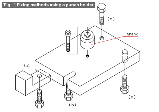
The method (a) assumes that the fixing is done using a clamp. The punch holder remains in the shape of a plate, and there is nothing addition to be done.
The method (b) is one in which the fixing by a bolt is done using a U-shaped groove. It is necessary to design the U-shaped groove to match with the size of the bolt.
The method of fixing (c) is one using a bolt and a hole drilled in the holder.
The method of fixing (d) is one using a bolt and a threaded hole drilled in the holder.
The above are the most commonly used methods for fixing a punch holder.

In the case of the methods (a), (b), and (c), the preparations become easy if the thickness of the punch holder is standardized.
In the case of the methods (b), (c), and (d), it is necessary to determine the position of the U-groove or the position of the hole to match with the specifications of the press machine.
The thickness of a punch holder is a very important factor. Its periphery can be left as it is in the welded state.
When it is necessary to align the center of the press machine and the center of the die, it is convenient if a positioning shank is affixed.

#131 Design of Blanking dies (4) Free Shank Design and Guide Post Length

A free shank (see Fig. 1) is made up of two -- a shank holder and a shank head. The shank holder is installed in the slide of the press machine, and the shank head is installed in the die. The installation is done so that the top part of the shank head is caught in the groove in the shank holder.
This shank has the function of transferring the pressing force to the punch holder and of pulling up the punch holder. There is a considerable play between the two parts.
Because of this, the relationship between the top die and the bottom die should always be maintained by the guide posts and the guide bushes.

Fig.1

Fig. 1 (a) shows the relationship between the post and the bush when the die is at the top dead center.
Fig. 1 (b) shows the relationship between the post and the bush when the die is at the bottom dead center.
At this time, it should be made sure that the top end of the post does not hit against the bottom surface of the slide.
When the punch and the die are reground, the die height becomes smaller thereby making the gap smaller between the top end of the post and the bottom surface of the slide. The design should be made such that this gap is present and there is no hitting of the one against the other even after regrinding has been repeated several times and the life of the die is approached.

There are two purposes of using a free shank.
One is to maintain the relationship between the punch and the die using posts and bushes, so that the work can be done without this relationship being affected by the press machine. The other is to simplify the setting up of the die.
The relationship between the post and the shank is explained below. See Fig. 2.

Fig.2

Care should be taken about the post length in the case of a die constituted as a die set.
Normally, as shown in Figure 2 (c), at the bottom dead center, it is ensured that the top end of the post is lower than the top surface of the punch holder (even when the die height has become lower after regrinding).
If due to some reason, the top end of the post projects beyond the top surface of the punch holder as shown in Figure 2 (d), a flange shank should be used thereby maintaining the relationship "s" between the bottom surface of the slide and the post.
A very serious accident will occur if the top end of the post hits against the bottom surface of the slide. Sufficient care should be given in the design regarding this aspect.

#130 Design of Blanking dies (3) Shank Design

The shank is used as a part for installing the top die in the slide of the press machine. This part is not limited to blanking dies, but is used commonly in all types of dies. We describe this first because it is basic information.

The relationship between the shank and the punch holder is shown in Fig. 1. The punch holder is the part being the base, and the shank is installed above it.

Fig. 1 Punch holder and shank

A shank is a part with the shape of a pillar, and is used for installing the top die of a relatively small die in the slide of the press machine. The standard diameters of the shank are 25, 32, 38, and 50 mm. These sizes are a legacy from the sizes in inches. Care should be taken because there are some old machines in which the size is not 25 mm but 25.4 mm. The lengths used are about 50 to 65 mm.
The materials used for shanks are SS400, S50C or equivalent, or FC250.

(1)Types of shanks (See Fig. 2)

Embedded shanks and flange shanks are used for fixing the top die. Apart from these, there are shanks for positioning and free shanks (see the descriptions in Lesson No. 171).

Fig, 2 Types of fixing shanks

(1) Embedded shank

One end of an embedded shank has threads cut on it. The shank is screwed into the hole in the punch holder. After firmly screwing down, sometimes some measure is taken to prevent it from rotating. This is procured at the time of ordering the die set very often.

(2) Flange shank A

This is a shank having a circular flange. Generally, the shank is installed at the center of the die. (In a die with an eccentric load, the position of the shank may be shifted to match with the eccentricity of the load.) In a die having the knock out mechanism (used frequently in blanking dies of the inverted placement structure), an embedded shank may become an obstruction. A flange shank is used in such situations.

(3) Flange shank B

This is a shank having a square flange. While a round flange shank can be machined integrally, this type of shank is very often prepared by combining a standard plate and an embedded shank. This is used when a large area is to be covered by the flange.

(4) Shank for positioning

When the die becomes large, it becomes dangerous to install and retain the top die using a shank (the top die can fall off). In such cases, the top die is fixed using a punch holder. However, when it is necessary to match the centers, a short one is used with respect to the diameter of the shank.

#129 Design of Blanking dies (2) Outline of Blanking Punch Design

In blanking work, the shape of the blanking punch is the same as the shape of the blanked product. The dimensions of the blanking punch at that time are made smaller than the blank dimensions by the amount of clearance.

* See also
Lesson 5:Clearance in the Blanking Operation
Lesson 11:Basics of Blanking Work (1) Blanking Work
Lesson 26:Basics of Die Structure (1) : Structure of Blanking Dies - 1

During the design, it is important to make the shape simple and easy to prepare. The changes depending on the size of the blanking punch are indicated below.

(1) Design of a large sized punch (See Fig. 1)

[Fig. 1] Design of a large sized punch

Since the punch area is large in the case of a large sized punch, it is possible to drill threaded holes for fixing the punch and holes for dowel pins (knock pins) inside that area.
This is shown schematically in Fig. 1 (a). This type of shape can be machined easily using a wire cut discharge machine.
Fig. 1 (b) is a standard shape of an assembly of the top die. The punch plate is omitted and the punch is directly installed to the punch holder thereby simplifying the structure. In the case of simple shapes such as a circle, etc., it is possible to prepare in further simplified manner by integrating the shank and the punch as shown in Fig. 1 (c). However, as explained in Lesson No. 168, the problem of adjusting the clearances of the punch and the die remains.

(2) Design of a medium sized punch (See Fig. 2)

[Fig. 2] Design of a medium sized punch

This is a type of punch whose size makes it difficult to drill threaded holes or knock holes inside it.
In the case of a simple shape such as a circle, etc., it is possible to provide a flange and to drill threaded holes or knock holes in the flange part, and to design again a structure in which the punch plate is omitted.
When the shape is complex, a flange is provided at a simple part, and the design is made in a similar fashion.
When this has been determined to be difficult to do, the punch will have to be fixed using a punch plate. Understand that the punch plate is not an indispensable part.

(3) Design of a small sized punch (See Fig. 3)

[Fig. 3] Design of punch and punch plate

When the product becomes small, even the punch becomes small. In that case, it becomes difficult to fix only the punch to the top die, and the method is used of fixing the punch after embedding it in a plate. This plate for fixing the punch is called a punch plate.
As shown in figure (f), the punch is made as straight as possible. When there is some problem in the strength due to the relationship between the size of the punch and the punch length, the design is made to provide a step in the punch. The relationship between the punch and the punch plate is designed so that the punch is lightly press fitted inside the hole in the punch plate (so that it can enter the hole with light hit with a plastic hammer).
This ensures the verticality and position of the punch.
Since it is difficult to ensure the verticality of the punch when it is fixed by swaging, this method should be avoided as far as possible.
It is standard practice to use S50C or SS400 as the material for the punch plate. The thickness should be about 30% to 40% of the punch length.

(4) Punch material

The standard punch material is SKD11. The heat treated hardness should be about 60 HRC.
The major method of preparing dies is using wire cut electric discharge machining. This is because the wire cut electric discharge machining is suitable for the material SKD11 and it is also good for wear resistance.
The punch material is changed taking SKD11 as the reference depending on the number of work steps, the material of the product to be worked, etc.

About this Archive

This page is an archive of entries from July 2012 listed from newest to oldest.

June 2012 is the previous archive.

August 2012 is the next archive.

Find recent content on the main index or look in the archives to find all content.