June 2012 Archives

#128 Design of Blanking dies (1) Outline of Blanking Die Design

(1) Outline of Dies

A blanking die is one which is used for producing contour shapes as is shown in Fig. 1. While the blanked contour becomes the contour of the product as it is in some cases, it is the developed shape of a product formed by bending or drawing, etc. in other cases. This can be said to be one of the basic press forming types. Fig. 1 Blanking

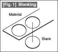
Fig. 2 shows the structure of a standard blanking die. This is a die of the fixed stripper structure. The blanking die is divided into a top die (which is constructed from a shank, a punch holder, a punch plate, and a punch) and a bottom die (which is constructed from a stripper, a die, and a die holder).

Fig. 2 Standard blanking die

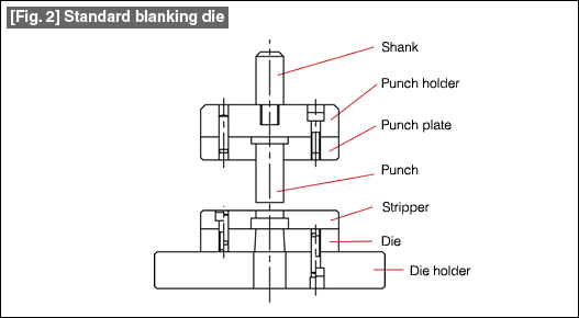
As shown in Fig. 3, the top die is installed to the slide of the press machine. In this example, the shank of the die is installed by fixing it using a shank holder. This is a method of installing the top die in the case of relatively small dies.

Fig. 3 Relationship between the press machine and the die

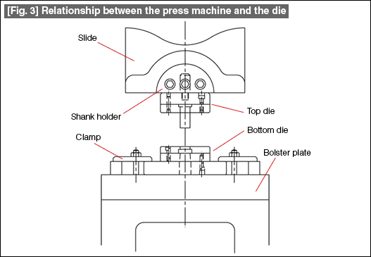
The bottom die is fixed using clamps on the bolster plate of the press machine. A very important factor in dies is the clearance.
In this example, the clearances of the punch and die are matched at the time of installing the die in the press machine. This type of die is called an open die. The operation of installing the die in the press machine is called "setting up the die". The clearance changes depending on the skill of the worker in setting up the die in the case of an open die.
This can also mean that the quality of the formed product is likely to change every time the die is set up.

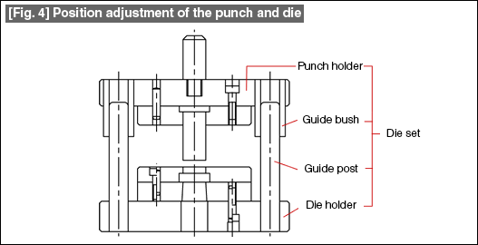
In order to solve this problem, a guide post and a guide bush are used as shown in Fig. 4 so that the relationship between the top die and the bottom die is maintained in the dies themselves. A large number of dies of this type are being used in which the relationship between the top die and the bottom die are maintained constant.
A unit in which the punch holder, guide bush, guide post, and the die holder are integrated into one single unit is called a "die set".
Further, a die of this shape is called a "die with a die set".

Fig. 4 Position adjustment of the punch and die

(2) Details of die design

Firstly, a die has a specific purpose of metal forming. In this case it is blanking. The functions necessary for blanking are to be understood first and then the concept is to be established.
Work is started after installing a die in the press machine. The method of installing the die is investigated and determined. In this example, the method of fixing used is that of fixing using a shank and a general purpose clamp.
In addition to take measures to make the setting up of the die easy, measures should be taken so that there is no fluctuation in the product quality even if the die is used repeatedly. In this example, the relationship between the die and the punch is maintained constant using a guide post and a guide bush (preventing fluctuations in the clearance), and setting up the die is made easy.
During die design, the necessary items are listed up, the policy is established, and then the detailed design is carried out.

#127 Press Forming Force (4) Drawing Force

The forming force (P) necessary for a cylindrical drawing is the force with which the punch pushes a circular blank into the die. The major factor related to the forming force is the resistance of the blank material to deformation. Apart from this, there is also the effect of the friction between the blank material and the die, the blank holding force (see course No. 10 for details of the blank holding force), etc. The sum of all these is the necessary drawing force.

The forming force of cylindrical drawing is determined very often using the following equation. Refer to Fig. 1.

P = K * π * d * t * Ts (kgf)
P: Drawing force (kgf)
K: Coefficient
π: Circumference ratio (3.14)
d: Drawing diameter (mm)
t: Plate thickness (mm)
Ts: Tensile strength (kgf)
[Fig.1] Drawing force

The factors having large influences on the drawing force are the tensile strength of the material, the drawing ratio, relative plate thickness (defined as material plate thickness / blank diameter * 100 (%)).
When the drawing ratio is fixed, the coefficient (K) becomes smaller as the relative plate thickness becomes larger, and on the contrary, becomes larger as the relative plate thickness becomes smaller. Its limiting value is 1.0.
In the above equation, the material cracks when K exceeds 1.
If the relative plate thickness is fixed, it changes depending on the drawing ratio.
The coefficient is given for reference in the example of a steel plate (SPC).
The following is the value of K when the relative plate thickness is 1.2%.

(1) Initial drawing

Drawing ratio (m) = 0.50 → K = 1.0
0.55 → K = 0.80
0.60 → K = 0.68
0.70 → K = 0.42

(2) Redrawing

Drawing ratio (m) = 0.75 → K = 0.90
0.80 → K = 0.62
0.82 → K = 0.52
0.85 → K = 0.42
0.90 → K = 0.20

When the drawing ratio is the same in both initial drawing and redrawing, the K value will be larger in redrawing. This is due to the effect of work hardening of the material.
The drawing force obtained by calculation appears considerably above the bottom dead center of the press machine. The press used is selected considering the torque capacity of the press machine.
The press machine is not selected based on the relationship between the drawing force and the nominal capacity of the press machine.

#126 Press Forming Force (3) Bending Force

The bending force discussed here is the force of forming a free bend. In bending operations, bottom bending is used frequently at the bottom dead center in order to stabilize the shape. An extremely large force is required in bottom bending depending on the amount of bottoming. The size of that force is considered to be 5 to 10 times the free bending force.

(1) Bending force for V-bending (See Fig. 1)

[Fig.1] V-Bending

The bending force for V-bending is obtained using the following equation.

 
  P: Bending force (kgf)
  C1: Coefficient
  B: Bending line length (mm)
  t: Plate thickness (mm)
  Ts: Tensile strength(Kgf/mm2

 The coefficient (C1) is 1.33 when the die shoulder width (L) is 8 times the material plate thickness (t), 1.5 when the die shoulder width is about 5 times the plate thickness, and about 1.2 when it is about 16 times the plate thickness.

(2) Bending force for L-bending (see Fig. 2)

[Fig.2] L-Bending

The bending force for L-bending is obtained using the following equation.

 P=C/3 * B * t * Ts(Kgf)
  P: Bending force (kgf)
  C: Coefficient ... 1.0 to 2.0
   (Select a larger coefficient when the punch R and the Die R are small.)
  B: Bending line length (mm)
  t: Plate thickness (mm)
  Ts: Tensile strength(Kgf/mm2

This shape is taken as the basis for the bending force for pad-pressed bending.
In the case of U-bending such as shown in Fig. 3, since the bending line (B) is present at two locations, the above calculation is made by doubling the vale of the bending line length (B) in the above equation.
  [Fig.3] U-Bending

In this manner, when bending is done in several locations at the same time, the total length of the bending lines is taken as the value of B.

About this Archive

This page is an archive of entries from June 2012 listed from newest to oldest.

May 2012 is the previous archive.

July 2012 is the next archive.

Find recent content on the main index or look in the archives to find all content.