Our discussion here covers an algorithm to obtain accurate Home Position using slotted photo sensors.
Method to accurately setup an accurate home position
The home position (= motor shaft angle origin position) is where the moving object's sensor target passes a photo sensor slot located in the middle. If the target passes with excessive speed, inertia of the moving object will cause a small overrun error causing inaccurate home position setting.
Homing routines are often performed when the system power is initially turned ON, and when emergency stops occur. It must be noted with caution that the routine may be performed manually at high speeds in order to save time.
Understanding the principle of machine homing and automating the routine with a homing program would save time.
|
For this reason, the sensor target must pass the sensor at low speeds. The algorithm below will shorten the time to perform the homing routine.
Accurate homing routine algorithm (see [Fig.])
![[Fig.1] Accurate homing routine algorithm](http://www.misumi-techcentral.com/tt/en/lca/images/039.gif)
| 1. | Approach the home position from one direction at a high speed, stop immediately when the home sensor is passed. | |
| 2. | Reverse the direction and approach at a low speed a point where the sensor turns OFF. | |
| 3. | Set this OFF point as the Home Position. |
Aim
1.will rapidly return the sensor target to the home sensor position.
2.enables the sensor to detect slowly moving target to avoid detection errors.


![[Fig.1]](http://www.misumi-techcentral.com/tt/en/lca/images/037_1.gif)
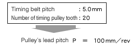
![[Fig.1] Timing belt driven single axis robot mechanism](http://www.misumi-techcentral.com/tt/en/lca/images/036_1.gif)
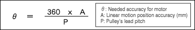
![[Fig.2] Needed motor accuracy and linear positioning accuracy](http://www.misumi-techcentral.com/tt/en/lca/images/036_3.gif)