August 2016 Archives

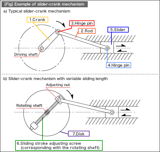
[Fig] a) is a slider-crank mechanism, which is a typical structure converting rotary motion into linear motion, achieved by connecting a slider and a crank with a rod. This mechanism is also utilized as a system that converts reciprocating linear motion of an automobile engine into rotary motion. (See [Fig.1] a.)

[Fig] b) is an example of the mechanism that has the same functions as [Fig] a), in addition to the sliding stroke adjustment feature for the slider. To add this feature, the sliding stroke adjusting screw is placed on top of the rotation shaft center of the rotation disk. The sliding stroke can be adjusted by the adjusting nut located on one end of the sliding stroke adjusting screw. This is an effective method if the mechanism shown in [Fig] a) needs to have a function that is compatible with various models. In addition, if high-speed rotation or operation for long hours is required, it is necessary to consider design items related to the reliability matters described here.

1. Rotation balance of rotating body (the entire structures on the disk)
2. Strength of rotating shaft
3. Prevention of adjusting nut-loosening (e.g. double-nut system)
4. Selection of wear-resistance parts for the area subject to wear

fig

•Example of standard component uses
Part No. Name Suggested MISUMI standard components
1. Crank LINS Series
2. Rod LINS Series
3. Hinge pin SCCGH Series
4. Hinge pin SCLBDG Series
5. Slider -
6. Sliding stroke adjusting screw FABS Series
7. Disk ENPNH Series

#250 Basic Elements of Automation Clever Mechanisms: Introduction

| No Comments | No TrackBacks

The basic element of clever mechanism are comprised of structures that transforms drive energy into motion control and equipped with two functions: motion transmission and power transmission. One automation mechanism can be utilized for both processing and control just by selecting the appropriate strength and material.

flowchart

Motion types constituting the Basic element of clever mechanical fixture include the followings:

1. Mechanism converting rotary motion into oscillation motion
2. Mechanism converting rotary motion into linear motion
3. Mechanism converting linear motion into rotary motion
4. Intermittent rotation and reciprocating motion mechanism
5. Speed-changing, speed reduction, and quick return mechanism
6. Direction-changing mechanism
7. Boost mechanism
8. Linear and parallel motion mechanism
9. Three-dimensional motion mechanism (using a cam mechanism)
10. Power transmission mechanism

First, we will look at a mechanism converting rotary motion into linear motion. Most of the mechanisms converting rotary motion into linear motion can also be used as a mechanism for converting linear motion into rotary motion by reversing the mechanisms. Since human motion is more compatible with the rotary motion task than the linear motion task, conversion from rotary into linear motion seems to be more common for simple fixtures.

(1) Mechanism converting rotary motion into linear motion

(1) Reciprocating linear motion by spiral groove (See [Fig.1])

By cutting a continuous spiral groove on the cam surface and placing an elliptical shape slider that slides along the spiral groove, the elliptical shape slider performs reciprocal linear motion according to the rotation of the cylindrical cam.

[Fig.1] Reciprocal linear motion conversion mechanism by spiral groove

The "beam" structure adds strength to construction and structural objects. The same concept will be utilized for cabinet design of mechanical devices. In this volume, we will learn about the types of beams and loads.

(1)Types of "beams"

Beams are generally available in the following five types:

a)Cantilever --- A beam structure anchored at only one end. The fixed side is called fixed end and the opposite is called free end.
b)Simply supported beam --- A beam structure where both ends of the beam are simply supported.
c)Overhanging beam --- A beam structure where loads are applied to the outside of the fulcrum.
d)Fixed beam --- A beam structure where both ends of the beam are fixedly supported.
e)Continuous beam --- A beam structure that is supported by three or more fulcrums.

fig

Description:

- Simple beams are adopted for SCARA (Selective Compliance Assembly Robot Arm) or the clamping arm mechanism (shown in Fig.a below) of a pick and place unit.

- Simply supported beams are adopted for the linear guide mechanism of shafts and ball bushing (see the below figure).

fig

(2)Types and expression of loads applied to the beam

- The case a) is a structure model that the mechanism is installed at the loaded area. The case b) is a model to adopt if you need to consider the effect of the weight of a beam itself.

fig

In this volume, we will learn about the energy (kinetic energy) that the movable part of a machine possesses.

(1) Kinetic energy

The energy that a moving object possesses is called "kinetic energy" (Ek).

- The joule (J) is used for the unit of kinetic energy.

- 1 J (joule) is equal to the work done to an object when a force of 1 N (Newton) acts on that object to move a distance of 1 m.

- The kinetic energy Ek (J) that an object with a mass m (kg) in motion at a velocity v (m/s) can be expressed in the following formula:

illust

(2) Machine safety mechanism for kinetic energy

- In a linear drive mechanism, a movable body continues its movement while possessing kinetic energy Ek.

- In case of accidents due to a lightning strike or power outage that could suspend the operation control, it is necessary to incorporate a safety mechanism into a machine in order to avoid damages and injuries caused by the kinetic energy that the movable body possesses.

- Installing a damper on both ends of the linear guide is a common method of incorporating a safety mechanism into a linear driving unit (see [Fig.1]).

- When you install an actuator with little frictional resistance into a linear motor mechanism, designing a safety mechanism is especially important. In such a case, large-sized dampers are adopted (see [Fig.2]).

[Fig.1] Example of safety mechanism in a linear motion unit

[Fig.2] Example of safety mechanism in a linear motor driving unit

月別 Archives

Pages

Powered by Movable Type 6.0.3

About this Archive

This page is an archive of entries from August 2016 listed from newest to oldest.

July 2016 is the previous archive.

September 2016 is the next archive.

Find recent content on the main index or look in the archives to find all content.