Here, we'll introduce some most advanced linear motion guide technology, levels above the slide guides.
High definition displays such as PC monitors and cellular phone displays require sub-micron level accuracies (i.e. 0.3 micrometers or better). Most of these key components are manufactured using ultra precision molds. To manufacture the molds, ultra precision machines that can achieve sub-micron level accuracies are used.
Typical examples of ultra precision machine.
Linear guide mechanism construction of the ultra precision machines can be categorized into the following two types.
|
a)Contacting slide guide ---- Rail and moving body move in contact
b)Non-contacting slide guide --- Rail and moving body move without contact |
|
(a)About contacting slide guide
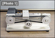
 | ・ | [Photo 1] below shows a representative configuration for a contacting slide guide for an ultra-precision machine. It uses a V-groove hand scraped by highly skilled operators and ultra precision grade roller bearings.
![[Photo 1] Configuration of an ultra precision linear guide [Photo 2] Hand scraping operation of linear guide way](http://www.misumi-techcentral.com/tt/en/lca/images/010_1.jpg) |
| ・ | Moving body and the roller bearings are placed on the hand scraped V-groove, and repeated adjustments are made using a measurement instrument. |
| ・ | This linear guide mechanism is driven by a ball screw. In order to negate any vertical errors that may be generated by the ballscrew deflection, the ballscrew nut is retained by parallel springs and only linear force is transmitted. |
(b)About non-contacting slide guide
| ・ |
|
shows an air bearing arrangement using Granite material typically used for surface plates.
|
|
![[Photo 3] Granite air bearing mechanism](http://www.misumi-techcentral.com/tt/en/lca/images/010_2.jpg) |
|
| ・ | Since the granite material is of natural origin, changes over time can be neglected, insensitive to temperature variation caused distortion, and vibration damping in nature. |
| ・ | The air bearing achieves ultra precise non-contacting linear guide by maintaining an air gap of approx. 6 micro meters with pressurized air. |
| ・ | The linear guide rail is a convex shaped block, and is hand finished by polishing for the final accuracy. |
| ・ |
|
Air bearing rigidity and resonance avoidance must be taken in consideration for the air pad design of the moving body [Photo 4]. |
|
![[Photo 4] Granite made air bearing slider](http://www.misumi-techcentral.com/tt/en/lca/images/010_3.jpg) |
|
| ・ | Sliver colored rectangular objects are linear motors. |
| ・ | Completely non-contacting linear guide mechanism is comprised of air bearings and linear motors. |
In the ultra precision motion control world as shown above, controlling the environment is required such as environmental temperature stabilization (i.e. within +/- 0.1 deg. C), independent foundation design for complete isolation from any external vibrations, and dust-less environment.
![[Fig.1]](http://www.misumi-techcentral.com/tt/en/lca/images/013_2.gif)
![[Fig.2]](http://www.misumi-techcentral.com/tt/en/lca/images/013_3.gif)
![[Fig.1]](http://www.misumi-techcentral.com/tt/en/lca/images/012_1.gif)
![[Photo 1]](http://www.misumi-techcentral.com/tt/en/lca/images/012_3.gif)