July 2009 Archives

#005 Usage Example of Shafts: Shaft Collar and Shaft Combinations

The shaft collars are useful in positioning applications for shafts and round posts. An usage example of stop position for shafts is described here.

Example 1 (Fig.1)

Shaft stopper mechanism with shaft collars with integrated dampers is explained.

 Fig.1
1. This example is a two shaft version of the single shaft linear motion system featured in Tutorial #002-b.
2. Since this is a cover open/close mechanism, the design does not account for excessive loads on the shafts and bearings.
3. The shaft has a pre-machined end needed for mounting: One end female thread type is selected. In order to prevent the mounting bolts from loosening, use flat washers and spring washers.
4. Thrust type oil-less short bushing is chosen as linear bearings for intermittent operation.
5. Shaft collars with integrated dampers are selected to establish the cover's stop position. In order to provide flat surfaces where the urethane dampers make contact, the oil-less bushings are fixed in place from below.
6. Although the moving cover is constricted by two shafts and an air cylinder rod, total of three shafts, the load is designed to be supported by the linear shafts and linear bearings. Use a floating joint to tie the air cylinder rod to the cover to prevent unnecessary loads on the air cylinder.
7. The structural material and surface treatment for corrosion prevention selection should be made based on the usage environmental condition, as well as reduction in cover weight for lightening the loads on the sir cylinder.

Below [Fig.1] and [Photo 1] show the design result following the guideline above.

image

#004 Installing Shafts - 2 : Practical Examples

Two cases will be introduced in terms of design features and maintainability. In case 1, the shafts are directly installed, and in case 2, the shafts are installed via shaft holder brackets.

Case 1 (See Figure 1)

The structure of the shaft with retaining ring groove is as follows:

1. The two bores on each of the two shaft fixing plates, through which both ends of the shafts are fixed, determine the parallelism of the two shafts. Therefore, the distance between the two bores on the shaft fixing plates should be specified with tolerance.
2. The precision of the shaft installing bores on the two shaft fixing plates must be specified with clearance fit (H7) that is required for precision fitting with minimal rattling.
3. Be sure to use large fixing bolts to secure the relative positions of the shaft fixing plates to the base plate.
4. The distance between the two retaining ring grooves on the shaft ends (distance L selectable in units of one millimeter) must be slightly longer than the outer distance between the two shaft fixing plates but without allowance in the longitudinal direction of the shafts.

image
Case 2 (See Figure 2)
The structure of the shaft holder bracket is as follows:
1. The parallelism of the two shafts is determined by the parallelism of the shaft holder bracket fixing plates (via which both ends of shafts are fixed) and by the precision of installing intervals of the shaft holder brackets.
2. Shaft holder brackets can be installed by tapping the shaft holder bracket fixing plates.
3. This structure assures high rigidity as the precision flanges hold the shafts.
4. Depending on the shape of the shaft ends on the opposite side, a variety of assembling procedures are possible. When shaft holder brackets are used for both sides, installation should be made by temporarily fixing the shafts, movable units and shaft holder brackets on the fixing plates before securing the plates on the peripheral structure. Also, be aware of the complexity of disassembling and maintenance of the shafts before starting the design of your mechanism.

image

#003 Installing Shafts - 1 : Variables in Execution

Installation of shafts depends on the design of the shaft holder that is constrained by the structure of the entire mechanism, requirements for ease of assembling and disassembling, and the limitation of the size of the mechanism.

(1)Reference planes of the base plate on which shafts are to be installed

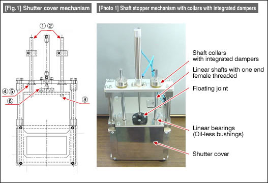
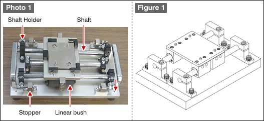
Shafts must be installed parallel to the reference planes so that the linear table can move accurately. Usually, the upper face and one end face of a shaft holder fixing plate (e.g., base plate) are used as the reference planes. (See Figure 1)

Example 1 (Figure 1)


(2)Shaft holders and shape of shaft ends

Shape of shaft ends suitable for the structure of your mechanism should be selected.

In the case of Figure 1, the base plate does not have any reference for positioning, thus two shafts are made parallel by the adjusting them during their installation.

Shape of shaft ends

Select straight type shaft ends. The shafts are fixed by shaft holders, thus the shaft ends do not need special machining.

Installing the shaft holders
1. Fix two shaft holders for securing the first shaft perpendicular to the face of the base plate.
2. Put one shaft through the bushing on one side of the movable table, install it onto the shaft holder, and fix the shaft to the shaft holder.
3. Put the other shaft through the movable table bushings, and temporarily loosely fasten the two shaft holders with fixing bolts.
4. Slide the movable table slowly to confirm that the table moves smoothly before you tighten the fixing bolts firmly.

images
Shape shaft ends

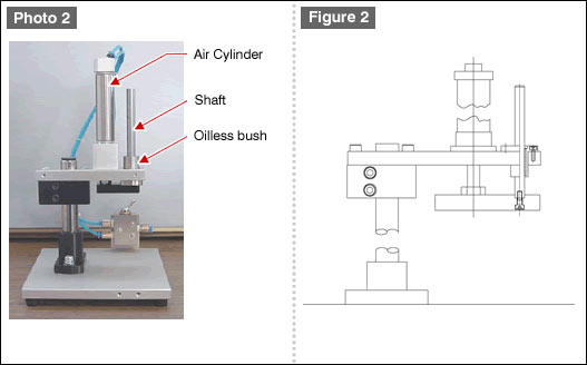
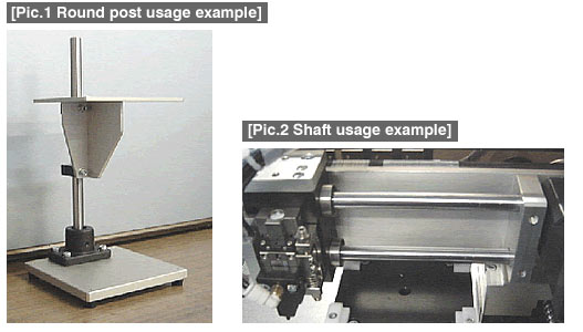
Figure 3 shows the structure in which the shaft is installed perpendicular to the shaft fixing plate to allow the air cylinder to move without adding any load.

images

Note: In order to install two shafts perpendicular to the shaft fixing plate, shafts with stepped and tapped ends are used. Dimensional accuracy and concentricity of the shouldered section allow the shafts to be fixed at a right angle.

#002 Precision Shafts

Due to their simple structure allowing high dimensional accuracy in machining, shafts are used for high precision linear guides. Misumi shafts feature:

Fit tolerance g6 (for requirement of precision motion with fine linear accuracy) or f8 (for use with grease or oil-lubricated bearings).
High surface hardness with employment of induction hardening and hard chromium plating.
Excellent circular tolerance and straightness plus concentricity and perpedicularity of finish ends.
A wide choice of end finishes.

Examples of linear motion applications using shaft(s)
a) Typical linear mechanism using two parallel shafts (see Figure 1 and Photo 1)
1. Using two shafts eliminates displacement, achieving high-precision linear motion capability and high load capacity. (See Photo 1)
2. Two types of bushings are available: linear bushings and oil-free bushings. Typically, linear bushings are used.
3. Oil-free bushings have high load capacity (compared to linear bushings) and are recommended for mechanisms subject to shock. Oil-free bushings, however, have larger friction resistance compared to linear bushings (which contain linear ball bearings), and should not be used for mechanisms subject to long continuous operations.

images

b)Linear mechanism using a single shaft (see Figure 2 and Photo 2)
1. With a linear mechanism using a single shaft, the shaft can serve as a motion guide involving linear and rotaty motions or as a linear guide by restraining rotation. Figure 2 shows the latter case.
2. The linear mechanism prevents rotation because the cylinder piston is acting as a second shaft. Therefore this configuration is not suitable for applications that require high load capacity. Photo 2 shows an example of using a linear shaft and air cylinder.
3. For a single-shaft mechanism, either long linear bushings (double-type or long-type) or oil-free bushings (for intermittent motions) should be selected to obtain linear stability and high load capability.

images

MISUMI's FA Mechanical catalog contains many components with similar appearances. However, they differ in design specifications such as material, surface treatments, dimensional tolerances and shaft-end configurations.

= Example: Case of [1] Shafts, [2] Rotary shafts, [3] Rods, and [4] Posts / Stands =
Explanation

our groups above have the similar appearances but with different functions

[1] Shafts and [2] Rotary shafts are motion mechanism components as moving parts.
[3] Rods and [4] Posts / Stands are structural components as non-moving parts.
For the motion mechanism components, material and surface treatments can be specified for durability, and tolerances for dimensional accuracy can be specified.

[Comparison table of four product groups]
Product nameMaterial
[JIS]
[ANSI]
[EN]
HardnessSurface treatmentO.D. tolerance and accuracy
Shafts
One end male thread type
equivalent

[S45C]
[1045 Steel]
[1.1191 / C45E
(Ck45)]


[SUS304]
[304 Stainless
Steel]

[1.4301 /
X5CrNi18-10]

58HRC〜
56HRC〜
(Induction hardening)
Hard Cr plating(HV750〜) Shaft O.D.: g6, f8 Circularity, Straightness, Verticalness, Concentricity can be Specified
Rotary shafts One end male thread type [S45C]
[1045 Steel]
[1.1191 /
C45E (Ck45)]


[SUS304]
[304 Stainless
Steel]

[1.4301 /
X5CrNi18-10]


[SCM435]
[4137 Alloy
Steel]

[1.7220 /
34CrMo4]
-Black oxide Electroless nickel plating Shaft O.D.: g6 Circularity, Straightness, Verticalness, Concentricity can be Specified
Thick-wall ground stainless steel pipe, male thread type [SUS304]
[304 Stainless
Steel]

[1.4301 /
X5CrNi18-10]

--Pipe O.D.: h8
Round posts One end male thread type [SS400]
[1018 Steel
Equivalent]

[1.0040 /
Ust.42.2]


[SUS304]
[304 Stainless
Steel]

[1.4301 /
X5CrNi18-10]
-Black oxide Electroless nickel plating Shaft O.D. : 0 -0.1

[Pic.1][Pic.2]

Organizing LCA mechanisms

The LCA is comprised of the following configuration, and this establishes the reference for the components' functionality.

LCA = Mechanism + Actuator + Controller

images

Structural member is: Non-moving mechanical elements that support the entire mechanism. Drive mechanism is: Moving mechanical elements.
In order to make proper product selections from the catalog, it is important to understand the specific characteristics of the listed components. We will explain the characteristics of the standard components using visual information such as photos and pictorials, hereafter. Usage examples of shafts will be explained with pictorials next.

月別 Archives

Pages

Powered by Movable Type 6.0.3

About this Archive

This page is an archive of entries from July 2009 listed from newest to oldest.

August 2009 is the next archive.

Find recent content on the main index or look in the archives to find all content.