November 2016 Archives

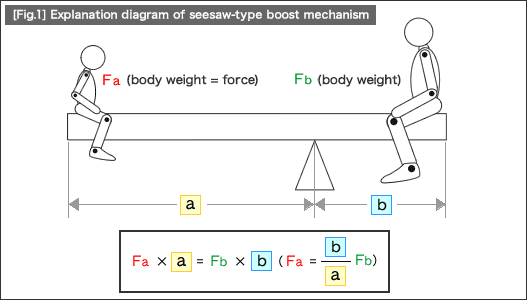
The simplest form of a boost mechanism is a seesaw seen in a playground. In this simple form, the boost mechanism is determined by the ratio of distance (arm length) from the fulcrum to the point of application of force. (See [Fig.1].) Bottle cap openers are another application example using the same principle as the seesaw.

fig1

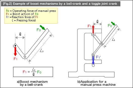
A bell-crank can be described as a bent version of the seesaw-type boost mechanism. The principle of the boost mechanism is the same, but because of the bent shape of the crank, the arm length is designed to be perpendicular to the direction of force applied, resulting in a different boosting effect ([Fig.2] - a)). A bell-crank is shaped the same as a nail puller used for carpentry work.

If you combine a bell-crank with a toggle joint crank, you will be able to create a simple manual pressing machine shown in [Fig.2] - b). In this mechanism, the force applied to the bell-crank handle (F0) is amplified by the bell-crank's boost mechanism in accordance with the arm length ratio and transformed into force (F1). The cabinet of the simple press machine supports this force. The toggle joint then diverts its reaction force toward the opposite direction, creating the pressing force (F1').

fig2

Application examples
1. Manual press machine
2. Manual swaging machine
3. Manual crimping machine, thermocompression bonding machine
4. Flatness correction

In the next volume, we will look at some more application examples of boost mechanisms using the power of leverage.

In this volume, we will look at an example of booster mechanisms for the press machine based on the piston-crank model.

The figure [a] below is a schematic view of the press machine. An eccentric disk is used for "Crank OA". When the center of this disk (center of gravity) comes below the center of rotation O, the weight of this disk acts on the presswork.

In the figure [b], the press machine [a] is expressed in the skeleton method. If we compare the vector components at "Joint A" in [b] and those at the pressing point "B", we can see that a booster action can be obtained from them. Using an eccentric disk amplifies "Tangential Force F0" acting on "Joint A". Then, the piston changes its force direction to vertical and forms "Press Force FP". In this figure, "Press Force FP" is approximately 1.4 times greater than "Tangential Force F0".

image

In the next volume, we will consider some application examples of the boost mechanisms using the power of leverage.

A mechanism designed to generate a large force from a small force is called a boost mechanism. Mechanical components that constitute this boost mechanism include links, levers, screws, wedges, gears, and pulleys. For lightweight arms of robots entered in the Robocon robot contest, the link mechanism is frequently adopted for its boosting effect produced from the simple structure.
Lifting up a heavy load using a lever is also an application example of this boost mechanism. In this case, you will be able to lift up a heavy load with a small force, but you will need to apply the force for a longer distance than when you carry the heavy load itself.
As you already know, using the boost mechanism does not change the workload (the force required for moving an object multiplied by the travel distance).

Now, let's take a look at the link mechanism consisting of four-bar linkages in [Fig.1] - a) and consider how the force vector is applied at Joint A.
[Fig.1] - b) is the schematic layout of a link mechanism generating a high degree of boosting effect.
[Fig.1] - c) is the schematic layout of a link mechanism generating little boosting effect.
Let's compare their force vector components at Joint A.

fig1

In [Fig.1] - b), "Crank OA" and "Link AB" form an angle of approximately 180 degrees (close to a linear arrangement) whereas "Link AB" and "Lever BC" are almost perpendicular to each other. In this case, if "Torque T" applies to "Driving Shaft OA" and Force F0 applies to the tangential direction of "Joint A", Force F1 applied to "Link AB" on "Joint A" will be 2.7 times greater than the tangential force F'0 based on the vector components at "Joint A".

In [Fig.1] - c) on the other hand, Force F'1 applied to "Link AB" on "Joint A" is only 1.1 times greater than the tangential force F'0.

As seen in this example, using the link mechanism to form the relationship shown in [Fig.1] - b), allows effective construction of the boost mechanism. In addition, when the link mechanism is applied to the boost mechanism, all the rotary couplers (in pairs) and the links must be designed with enforced strength.

In the next volume, we will look at an application example of the boost mechanisms using a crank.

When rotation axes are located on the same plane and placed at 90 degrees or more to each other, rotation of the driving shaft can be transmitted to the driven shaft by connecting the two axes using a coil spring. (See [Fig.1] for details.)

[Fig.1] Example of direction-changing mechanism using a coil spring

Since the direction-changing unit connected with this coil spring can be designed with some flexibility as long as the driven shaft axis is 90 degrees or larger, it will be utilized for mechanisms requiring assembly adjustment or sorting by the products' grade and more.
[Fig.2] illustrates examples of a driven shaft connection for a mechanism compatible with various models.

[Fig.2] Structural example of a quick shaft joint

Because a coil spring is used for connecting the component, the following disadvantages must be kept in mind when designing this mechanism.

Disadvantages (limitation of rotary diversion performance)
  1. When the angle (θ in Fig.1) of the two axes become small (less than 90 degrees), the rotary transmission becomes unstable.
  2. Adopting this mechanism to a system involving high-speed rotation or varying rotation speed will result in less precision.
  3. The helical direction of a coil spring must be same as the direction of shaft rotation.
  4. The coil spring may fracture owing to fatigue.

Application examples
  1. Rotation adjustment mechanism compatible with various models
  2. Transmission mechanism having a small rotary torque
  3. Simple adjustment mechanism in a rotary system

In the next volume, we will learn about the boost mechanism designed to generate a large force from a small force (human power).

月別 Archives

Pages

Powered by Movable Type 6.0.3

About this Archive

This page is an archive of entries from November 2016 listed from newest to oldest.

October 2016 is the previous archive.

December 2016 is the next archive.

Find recent content on the main index or look in the archives to find all content.